Bestückung von Einzelkontakten
In den nachfolgenden Abschnitten wird ein Überblick über die in der Kontakttechnik üblicherweise verwendeten Bestückungsverfahren von vorgefertigten Kontaktträgerteilen mit Kontaktmaterial gegeben. Zu diesen Verfahren zählen die mechanische Bestückung, das Löten und das Schweißen.
Mechanische Bestückungsverfahren
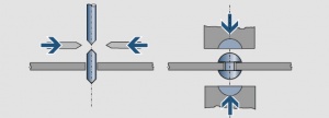
Das Einnieten von Kontaktnieten sowie das Einpressen und Formen von Drahtabschnitten in gelochte Kontaktträger sind vielfach angewandte Verfahren der mechanischen Bestückung von Kontaktträgern mit Kontaktmaterial.
Das Einnieten wird bei kleineren Stückzahlen meist mittels Exzenterpresse oder durch pneumatische oder magnetische Druckerzeugung ausgeführt. Bei großen Stückzahlen erfolgt der Prozessablauf meist in Folgeverbundwerkzeugen vollautomatisch, wobei die Kontaktniete über geeignete Zuführungen lagerichtig zur Montagestation gelangen. Zur sicheren Befestigung muss der Schließkopf ausreichend bemessen sein. Als Faustregel gilt, dass der Schaft mindestens um 1/3 länger, als der Kontaktträger dick ist. Bei der Herstellung von Umschaltkontakten wird ein Teil des Nietschaftes zu einem zweiten Kontaktkopf umgeformt. Um Deformationen vor allem bei dünnen Kontaktträgern zu vermeiden, erfolgt der Nietvorgang meist durch Rollieren oder Taumeln.
Das Einpressen von Drahtabschnitten lässt sich besonders gut in ein Stanz- Biege-Werkzeug integrieren Figure 1. Dem im Vergleich zu plattierten Kontaktnieten höheren Edelmetallverbrauch steht dabei eine höhere Arbeitsgeschwindigkeit gegenüber, die dieses Verfahren bei silberhaltigen Kontakten wirtschaftlich macht. Allerdings besteht bei der Verarbeitung von Drahtabschnitten aus sprödem Ag/SnO2-Vormaterial die Gefahr der Rissbildung.
Lötverfahren
Löten ist ein thermisches Verfahren zum stoffschlüssigen Fügen metallischer Werkstoffe mit Hilfe eines geschmolzenen Zusatzwerkstoffes (Lot), gegebenenfalls unter Verwendung von Flussmittel oder Schutzgas. Der Schmelzbereich des Lotes umfasst den Temperaturbereich vom Beginn des Schmelzens (Solidustemperatur) bis zur vollständigen Verflüssigung (Liquidustemperatur). Er liegt unterhalb der Schmelzbereiche der zu fügenden Teile. Beim Lötvorgang kommt es bei gegenseitiger Löslichkeit durch thermische Aktivierung zu Diffusionsvorgängen, bei denen sowohl Elemente des Lotes in den Grundwerkstoff als auch Elemente des Grundwerkstoffes in das Lot eindringen. Dadurch wird eine Verstärkung der Haftkräfte und somit eine Erhöhung der mechanischen Belastbarkeit erreicht.
Zur Befestigung von Kontaktplättchen auf Trägerteilen werden ausschließlich Hartlote verwendet. Gründe hierfür sind ihre im Vergleich zu Weichloten höhere Erweichungs- und Schmelztemperatur, höhere mechanische Festigkeit und günstigere elektrische Leitfähigkeit. Die für elektrische Kontakte eingesetzten Lote und Flussmittel werden in Kap. 4 (Lote und Flussmittel) und unter Prüfung von Löt- und Schweißverbindungen behandelt. Nachfolgend werden einige häufig verwendete Lötverfahren beschrieben.
Flammlöten
Am einfachsten lässt sich das Hartlöten mit Hilfe eines Gebläsebrenners ausführen. Bei hinreichend großen Stückzahlen wird das Flammlöten häufig teilautomatisiert. Dabei durchlaufen die zu lötenden Teile, nachdem sie mit dosierten Lot- und Flussmittelmengen versehen wurden, eine Reihe feststehender Brenner eines Lötkarussells oder einer Förderbandlötmaschine. Um den Anteil an Flussmittel- und Gaseinschlüssen in der Lotschicht einzuschränken, empfiehlt es sich, sobald das Lot schmelzflüssig ist, die Kontaktauflagen etwas hin- und herzubewegen (einzuschwemmen). Der Lotbindungsanteil liegt beim Flammlöten je nach Größe und geometrischer Form der Verbindungsflächen zwischen 65% und 90%.
Ofenlöten
Unter dem Begriff Ofenlöten wird vor allem das Schutzgaslöten und das Vakuumlöten verstanden. Beide Verfahren arbeiten flussmittelfrei.
Das Schutzgaslöten erfolgt entweder als diskontinuierliche Lötung in Muffel-, Topf- oder Haubenöfen oder als kontinuierliche Lötung in Förderbanddurchlauföfen in reduzierender Atmosphäre in reinem Wasserstoff (H2) oder Ammoniakspaltgas (H2,N2).
A vacuum is a very efficient protective environment for brazing but using vacuum furnaces is more complicated and rather inefficient. Therefore this process is only used for materials and assemblies that are sensitive to oxygen, nitrogen, or hydrogen impurities. Not suitable for vacuum brazing are materials which contain components with a high vapor pressure.
Das Vakuum ist ein sehr wirkungsvolles „Schutzgas“. Da das Vakuumlöten verhältnismäßig aufwändig ist, werden meist nur solche Werkstoffe gelötet, die während des Lötprozesses sehr empfindlich sind gegenüber Sauerstoff-, Stickstoff- oder Wasserstoffverunreinigungen. Für eine Vakuumlötung ungeeignet sind Werkstoffe, die Bestandteile mit hohem Dampfdruck enthalten.
Teile aus sauerstoffhaltigem Kupfer dürfen nicht in reduzierender Atmosphäre gelötet werden, da sonst die sog. Wasserstoffkrankheit auftritt. Ähnliches gilt für metalloxidhaltige Kontaktwerkstoffe, da durch Reduzierung des Metalloxids die Werkstoffzusammensetzung und dadurch die Kontakteigenschaften in der oberflächennahen Schicht geändert werden.
Widerstandslöten
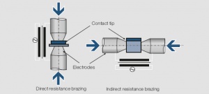
Bei diesem Lötvorgang dient die Widerstandserwärmung unter Stromfluss als Energiequelle. In der Kontakttechnik werden für das Widerstandslöten zwei Verfahrensvarianten angewandt Figure 2.
Beim direkten Widerstandslöten fließt der Strom unmittelbar durch die Lötfläche. Kontaktauflage und Trägerteil werden dabei zusammen mit Lot und Flussmittel zwischen die Elektroden einer Widerstandslötmaschine gespannt und durch direkten Stromdurchgang so lange erwärmt, bis das Lot in der Verbindungsfläche zum Schmelzen kommt.
Beim indirekten Widerstandslöten fließt der Strom nur über eines der zu verbindenden Werkstücke. Diese Verfahrensvariante bietet die Möglichkeit, die Kontaktauflage im schmelzflüssigen Lot hin-und herzubewegen (einschwemmen) und Lunkerstellen, verursacht durch Flussmitteleinschlüsse, aus dem Fügebereich zu entfernen und so den Bindeanteil zu erhöhen. Für das Widerstandslöten werden zwei Arten von Elektrodenwerkstoffen eingesetzt:
- Elektroden aus schlecht leitenden Kohlewerkstoffen (Grafit))
Die Wärme wird in den Elektroden erzeugt und durch Wärmeleitung zur Verbindungsfläche transportiert.
- Elektroden aus gut leitenden, warmfesten Metallen.
Die Wärme wird durch den erhöhten elektrischen Widerstand in der Verbindungsfläche, die durch geeignete Gestaltung eine ausgeprägte Stromenge darstellt, und durch den Widerstand der Werkstücke erzeugt.
Kohleelektroden kommen vor allem beim indirekten Widerstandslöten und bei Verbindungsflächen > 100 mm2 zum Einsatz. Bei Kontaktauflagen < 100 mm2, die bereits mit phosphorhaltigem Silber-Hartlot beschichtet sind, kann beim direktem Widerstandslöten die Lötzeit so kurz gehalten werden, dass die Trägerteile nur in unmittelbarer Nähe der Fügefläche erweichen. Für dieses „Kurzzeitlöten“ werden meist warmfeste Metallelektroden verwendet, deren Werkstoffzusammensetzung und geometrische Form den jeweils zu verbindenden Teilen angepasst sind.
Der Bindeanteil der gelöteten Fläche liegt beim üblichen Widerstandslöten mit Flussmittel je nach Kontaktgröße zwischen 70% und 90%, beim Kurzzeitlöten deutlich höher.
Induktionslöten
Beim Induktionslöten ensteht die Wärme über einen Induktor, der von einem Mittel- oder Hochfrequenzgenerator gespeist wird und ein elektromagnetisches Wechselfeld zur Folge hat, das im Lotgut Wirbelströme erzeugt. Aufgrund des Skineffektes erfolgt der Stromfluss und dadurch auch die Erwärmung bevorzugt in der Außenschicht des Werkstücks. Der Abstand des Heizinduktors zum Lötgut muss so gewählt werden, dass auf der gesamten Lötfläche möglichst gleichzeitig die Arbeitstemperatur erreicht wird. Das Induktionslöten kann für verschiedenste Kontaktformen durch geeignete Formgebung des Induktors optimiert werden. Ein Vorteil dieses Verfahrens liegt in der kurzen Aufheizzeit, so dass nur die der Lötzone unmittelbar benachbarten Bereiche erweichen. Die teilweise sehr unterschiedlichen Lötzeiten bei den verschiedenen Lötverfahren sind aus der nachfolgenden Table 1 zu entnehmen.
| Lötverfahren | Lötzeit in s |
|---|---|
| Flammenlöten | 3 - 100 |
| direktes Widerstandslöten | 1 - 3 |
| indirektes Widerstandslöten | 1 - 5 |
| Kurzzeitlöten | 0.1 - 1 |
| Induktionslöten | 0.5 - 5 |
| Ofenlöten | 100 - 1000 |
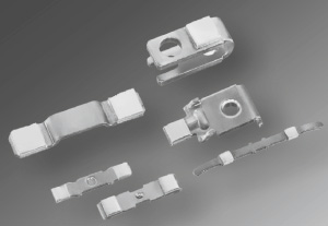
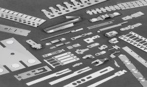
- Beispiele für gelötete Kontaktteile Figure 3
- Kontaktwerkstoffe
Ag, Ag-Alloys., Ag/Ni (SINIDUR), Ag/CdO (DODURIT CdO), Ag/SnO2 (SISTADOX), Ag/ZnO (DODURIT ZnO) and Ag/C (GRAPHOR D) mit lötbarer Unterseite, Refraktäre Werkstoffe auf W -, WC- und Mo-Basis
- Lote
L-Ag 15P, L-Ag 55Sn u.a.
- Trägerwerkstoffe
Cu, Cu-Alloys. u.a.
- Abmessungen
Lötfläche > 10 mm²
- Qualitätsmerkmale
Die Prüfung der Lötverbindung erfolgt nach Vereinbarung zwischen Hersteller und Anwender.
Schweißverfahren
Für das Schweißen als Verbindungsverfahren sprechen sowohl technische als auch wirtschaftliche Gesichtspunkte. Aufgrund der kurzzeitigen Wärmeeinwirkung bleibt bei allen Schweißverfahren die Ausgangshärte der Trägerteile bis auf den unmittelbar thermisch beanspruchten Bereich erhalten. Unter den nachfolgend beschriebenen Schweißverfahren nimmt das Widerstandsschweißen eine Vorrangstellung ein.
Because of miniaturization of electromechanical components laser welding has gained some application more recently. Friction welding is mainly used for bonding see Applications for Bonding Technologies. Other welding methods such as ball (spheres) welding and ultrasonic welding are today used in only limited volume and therefore not covered in detail here. Special methods such as electron beam welding and cast-on attachment of contact materials to carrier components are mainly used for contact assemblies for medium and high voltage switchgear.
Resistance Welding
Resistance welding is the process of electrically joining work pieces by creating the required welding energy through current flow directly through the components without additional intermediate materials. For contact applications the most frequently used method is that of projection welding. Differently shaped weld projections are used on one of the two components to be joined (usually the contact). They reduce the area in which the two touch creating a high electrical resistance and high current density which heats the constriction area to the melting point of the projections. Simultaneously exerted pressure from the electrodes further spreads out the liquefied metal over the weld joints area. The welding current and electrode force are controlling parameters for the resulting weld joint quality. The electrodes themselves are carefully designed and selected for material composition to best suit the weld requirements.
The waveform of the weld current has a significant influence on the weld quality. Besides 50 or 60 Hz AC current with phase angle control, also DC (6-phase from 3-phase rectified AC) and medium frequency (MF) weld generators are used for contact welding. In the latter the regular AC supply voltage is first rectified and then supplied back through a controlled DC/AC inverter as pulsed DC fed to a weld transformer. Medium frequency welding equipment usually works at frequencies between 1kHz to 10kHz. The critical parameters of current, voltage, and weld energy are electronically monitored and allow through closed loop controls to monitor and adjust the weld quality continuously. The very short welding times needed with these MF welding machines result in very limited thermal stresses on the base material and also allow the reliable joining of otherwise difficult material combinations.
Vertical Wire Welding
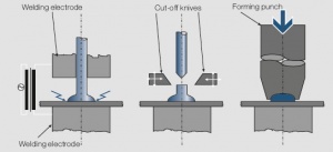
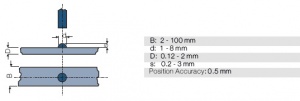
During vertical wire welding the contact material is vertically fed in wire form through a clamp which at the same time acts as one of the weld electrodes Figure 4.
With one or more weld pulses the roof shaped wire end – from the previous cut-off operation – is welded to the base material strip while exerting pressure by the clamp-electrode. Under optimum weld conditions the welded area can reach up to 120% of the original cross-sectional area of the contact wire. After welding the wire is cut off by wedge shaped knives forming again a roof shaped weld projection. The welded wire segment is subsequently formed into the desired contact shape by stamping or orbital forming. This welding process can easily be integrated into automated production lines. The contact material must however be directly weldable, meaning that it cannot contain graphite or metal oxides.
Horizontal Wire or Profile Welding
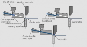
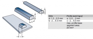
During horizontal welding the wire or profile contact material is fed at a shallow angle to the carrier strip material Figure 5.
The cut-off from the wire or profile is performed either directly by the electrode or in a separate cutting station. This horizontal feeding is suitable for welding single or multiple layer weld profiles. The profile construction allows to custom tailor the contact layer shape and thickness to the electrical load and required number of electrical switching operations. By choosing a two-layer contact configuration multiple switching duty ranges can be satisfied. The following triple-layer profile is a good example for such a development: The top 5.0 μm AuAg8 layer is suitable to switch dry circuit electronic signals, the second or middle layer of 100 μm Ag/Ni 90/10 is used to switch relative high electrical loads and the bottom layer consists of an easily weldable alloy such as CuNi44 or CuNi9Sn2. The configuration of the bottom weld projections, i.e. size, shape, and number of welding nibs or weld rails are critically important for the final weld quality.
Because of high production speeds (approx. 700 welds per min) and the possibility to closely match the amount of precious contact material to the required need for specific switching applications, this joining process has gained great economical importance.
Tip Welding
Contact tips or formed contact parts produced by processes as described in Contact Tips are mainly attached by tip welding to their respective contact supports. In this process smaller contact parts such as Ag/C or Ag/W tips with good weldable backings are welded directly to the carrier parts. To improve the welding process and quality the bottom side of these tips may have serrations (Ag/C) or shaped projections (Ag/W). These welding aids can also be formed on the carrier parts. Larger contact tips usually have an additional brazing alloy layer bonded to the bottom weld surface.
Tip welding is also used for the attachment of weld buttons (see Weld Buttons). The welding is performed mostly semi or fully automated with the buttons oriented a specific way and fed into a welding station by suitably designed feeding mechanisms.
Percussion Welding
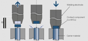
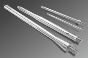
This process of high current arc discharge welding required the contact material and carrier to have two flat surfaces with one having a protruding nib. This nib acts as the igniter point for the high current arc Figure 6.
The electric arc produces a molten layer of metallic material in the interface zone of the contact tip and carrier. Immediately afterwards the two components are pushed together with substantial impact and speed causing the liquid metal to form a strong joint across the whole interface area. Because of the very short duration of the whole melt and bonding process the two components, contact tip and carrier, retain their mechanical hardness and strength almost completely except for the immediate thin joint area. The unavoidable weld splatter around the periphery of the joint must be mechanically removed in a secondary operation. The percussion welding process is mainly applied in the production of rod assemblies for high voltage switchgear.
Laser Welding
This contact attachment process is also one of the liquid phase welding methods. Solid phase lasers are predominantly used for welding and brazing. The exact guiding and focusing of the laser beam from the source to the joint location is most important to ensure the most efficient energy absorption in the joint where the light energy is converted to heat. Advantages of the method are the touch-less energy transport which avoids any possible contamination of contact surfaces, the very well defined weld effected zone, the exact positioning of the weld spot and the precise control of weld energy.
Laser welding is mostly applied for rather small contact parts to thin carrier materials. To avoid any defects in the contact portion, the welding is usually performed through the carrier material. Using a higher power laser and beam splitting allows high production speeds with weld joints created at multiple spots at the same time.
Special Welding and Attachment Processes
In high voltage switchgear the contact parts are exposed to high mechanical and thermal stresses. This requires mechanically strong and 100% metallurgically bonded joints between the contacts and their carrier supports which cannot be achieved by the traditional attachment methods. The two processes of electron beam welding and the cast-on with copper can however used to solve this problem.
Electron Beam Welding
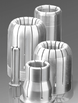
The electron beam welding is a joining process which has shown its suitability for high voltage contact assemblies. A sharply focused electron beam has sufficient energy to penetrate the mostly thicker parts and generate a locally defined molten area so that the carrier component is only softened in a narrow zone (1 – 4 mm). This allows the attachment of Cu/W contacts to hard and thermally stable copper alloys as for example CuCrZr for spring hard contact tulips Figure 7.
Cast-On of Copper
The cast-on of liquid copper to pre-fabricated W/Cu contact parts is performed in special casting molds. This results in a seamless joint between the W/Cu and the copper carrier. The hardness of the copper is then increased by a secondary forming or deep-drawing operation.
- Examples of Wire Welding (Figure 8)
Vertical Wire Welding
- Contact materials
Ag, Ag-Alloys, Au- and Pd-Alloys, Ag/Ni (SINIDUR)
- Carrier materials
Cu, Cu-Alloys, Cu clad Steel, et.al.
- Dimensions Figure 9
Functional quality criteria such as bonded area percentage or shear force are usually agreed upon between the supplier and user and defined in delivery specifications.
Horizontal Wire Welding
- Contact materials
Au-Alloys, Pd-Alloys, Ag-Alloys, Ag/Ni (SINIDUR), Ag/CdO (DODURIT CdO), Ag/SnO2 (SISTADOX), Ag/ZnO (DODURIT ZnO), and Ag/C (GRAPHOR D)
- Carrier materials
(weldable backing of multi-layer profiles) Ni, CuNi, CuNiFe, CuNiZn, CuSn, CuNiSn, and others.
- Braze alloy layer
L-Ag 15P (CP 102 or BCUP-5)
- Dimensions Figure 10
- Quality criteria
Functional quality criteria such as bonded area percentage or shear force are usually agreed upon between the supplier and user and defined in delivery specifications.
Percussion Welding
- Contact materials
W/Cu, W/Ag, others
- Carrier materials
Cu, Cu-Alloys, others
- Dimensions
Weld surface area (flat) 6.0 to 25 mm diameter
Rectangular areas with up to 25 mm diagonals
- Quality criteria
Test methods for bond quality are agreed upon between supplier and user
Figure 11
