Difference between revisions of "Herstellung von Halbzeugen"
Teitscheid (talk | contribs) (temp edit) |
Teitscheid (talk | contribs) (temp edit) |
||
| Line 20: | Line 20: | ||
beschrieben werden. | beschrieben werden. | ||
| − | + | Beim Warmpressschweißen, dem klassischen Plattierverfahren, werden die zu | |
| − | 800°C | + | verbindenden Werkstoffe in Blockform zu einem Schweißpaket zusammengestellt, |
| + | auf ca. 800°C erwärmt und unter hohem Pressdruck verschweißt | ||
| + | <xr id="fig:Hot_cladding_of_pre_materials"/><!--(Fig. 3.3)-->. Dabei entsteht in der Berührungsfläche der beiden Werkstoffe eine | ||
| + | unlösbare stoffschlüssige Verbindung entweder in fester Phase durch Diffusion | ||
| + | der Reaktionspartner oder in flüssiger Phase mittels einer zwischengelegten | ||
| + | Lotfolie bzw. durch Bildung eines AgCu-Eutektikums. Die Weiterverarbeitung | ||
| + | des Werkstoffverbundes erfolgt durch Walzen mit entsprechenden Zwischenglühungen. Der Nachteil dieser Plattiertechnik liegt verfahrensbedingt in den kurzen | ||
| + | Fertigungslängen. | ||
<figure id="fig:Hot_cladding_of_pre_materials"> | <figure id="fig:Hot_cladding_of_pre_materials"> | ||
| − | [[File:Hot cladding of pre-materials (schematisch).jpg|right|thumb| | + | [[File:Hot cladding of pre-materials (schematisch).jpg|right|thumb|Warmpressschweißen von Kontaktbimetall (schematisch)]] |
</figure> | </figure> | ||
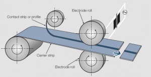
| − | + | Beim Kaltwalzplattieren erfolgt die Verbindung zwischen Kontakt- und Trägerwerkstoff | |
| + | durch eine Kaltumformung > 50% in einem Stich <xr id="fig:Cold roll-cladding of semi-finished strips (schematic)"/><!-- (Fig. 3.4)-->. Durch die | ||
| + | starke plastische Verformung kommt es in der Grenzschicht zwischen den | ||
| + | Plattierpartnern zu einer Kaltverschweißung. Um die Qualität der Schweißverbindung | ||
| + | zu verbessern wird anschließend meist eine Diffusionsglühung | ||
| + | durchgeführt. Dieses Fertigungsverfahren ist besonders zur Herstellung von | ||
| + | plattiertem Halbzeug mit dünnen Kontaktauflagen (>2 μm) und großen | ||
| + | Bandlängen (>100 m) geeignet. | ||
<figure id="fig:Cold roll-cladding of semi-finished strips (schematic)"> | <figure id="fig:Cold roll-cladding of semi-finished strips (schematic)"> | ||
| − | [[File:Cold roll-cladding of semi-finished strips (schematic).jpg|right|thumb| | + | [[File:Cold roll-cladding of semi-finished strips (schematic).jpg|right|thumb|Kaltwalzplattieren von Kontaktbimetall ( schematisch)]] |
</figure> | </figure> | ||
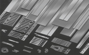
| − | * | + | *Typische Ausführungsformen für Kontaktbimetalle <xr id="fig:Typical configurations of clad contact strips"/> |
<figure id="fig:Typical configurations of clad contact strips"> | <figure id="fig:Typical configurations of clad contact strips"> | ||
| − | [[File:Typical configurations of clad contact strips.jpg|right|thumb| | + | [[File:Typical configurations of clad contact strips.jpg|right|thumb|Typische Ausführungsformen für Kontaktbimetalle]] |
</figure> | </figure> | ||
| − | * | + | *Kontaktwerkstoffe <br />Ag, Ag-alloys., Ag/Ni (SINIDUR), in Sonderfällen auch Ag/CdO (DODURIT CdO), Ag/SnO<sub>2</sub> (SISTADOX), Ag/ZnO (DODURIT ZnO)<br /> |
| − | * | + | *Trägerwerkstoffe<br />Cu, CuSn, CuNiZn, CuNiSn, CuFe, CuBe u.a. |
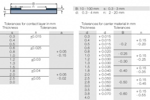
| − | * | + | *Abmessungen <xr id="fig:Dimensions"/> |
<figure id="fig:Dimensions"> | <figure id="fig:Dimensions"> | ||
| − | [[File:Dimensions.jpg|right|thumb| | + | [[File:Dimensions.jpg|right|thumb|Abmessungen]] |
</figure> | </figure> | ||
| − | + | Bei der Festlegung der Dicke der Edelmetalleinlage wird empfohlen, den | |
| + | Minimalwert anzugeben. | ||
| − | * | + | *Qualitätsmerkmale und Toleranzen |
| − | + | Festigkeitswerte und Maßtoleranzen von Kontaktbimetallen sind an die für Cu | |
| + | und Cu-Legierungen geltenden Normen EN 1652 und EN 1654 angelehnt. Bei | ||
| + | der Vermaßung der Breite der Edelmetalleinlage wird empfohlen, von den für die | ||
| + | jeweilige Anwendung erforderlichen Minimalwerten auszugehen. Die Vermaßung | ||
| + | sollte stets von der Bandkante aus erfolgen.. | ||
| − | === | + | ===Gelötete Halbzeuge (Toplay-Profile)=== |
| − | + | Das Toplay-Verfahren geht von einem flachen oder profilierten edelmetallhaltigen | |
| + | Kontaktband aus, das zusammen mit einem Hartlotstreifen und dem | ||
| + | unedlen Trägerband einem Induktions-Lötautomaten zugeführt wird <xr id="fig:Toplay brazing with an inductive heating inline equipment (schematic)"/><!--(Fig. 3.5)-->. | ||
| + | Dabei lässt sich eine gleichmäßige und zuverlässige Lötverbindung zwischen | ||
| + | Kontaktauflage und Trägermaterial herstellen. Der so erzeugte Werkstoffverbund | ||
| + | mit erhabener Edelmetallauflage ist nach dem Löten weich und wird | ||
| + | anschließend auf profilierten Walzen nachverfestigt. Auf diese Weise können | ||
| + | unterschiedliche Profilformen hergestellt werden. | ||
<figure id="fig:Toplay brazing with an inductive heating inline equipment (schematic)"> | <figure id="fig:Toplay brazing with an inductive heating inline equipment (schematic)"> | ||
| − | [[File:Toplay brazing with an inductive heating inline equipment (schematic).jpg|right|thumb|Toplay | + | [[File:Toplay brazing with an inductive heating inline equipment (schematic).jpg|right|thumb|Toplay-Lötung mit Induktionsdurchlaufanlage (schematisch)]] |
</figure> | </figure> | ||
| − | * | + | *Typische Ausführungsformen für Toplay-Profile <xr id="fig:Typical configurations of toplay contact profiles2"/> |
<figure id="fig:Typical configurations of toplay contact profiles2"> | <figure id="fig:Typical configurations of toplay contact profiles2"> | ||
| − | [[File:Typical configurations of toplay contact profiles2.jpg|right|thumb| | + | [[File:Typical configurations of toplay contact profiles2.jpg|right|thumb|Typische Ausführungsformen für Toplay-Profile]] |
</figure> | </figure> | ||
| − | * | + | *Kontaktwerkstoffe <br />Ag, AgNi 0,15 (ARGODUR), AgCu, AgCuNi (ARGODUR 27), Ag/Ni (SINIDUR), |
Ag/CdO (DODURIT CdO), Ag/SnO<sub>2</sub> (SISTADOX), Ag/ZnO (DODURIT ZnO)<br /> | Ag/CdO (DODURIT CdO), Ag/SnO<sub>2</sub> (SISTADOX), Ag/ZnO (DODURIT ZnO)<br /> | ||
| − | * | + | *Trägerwerkstoffe <br />Cu, CuZn, CuSn u.a.<br /> |
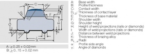
| − | * | + | *Qualitätsmerkmale, Abmessungen und Toleranzen <xr id="fig:Quality criteria dimensions and tolerances"/> |
<figure id="fig:Quality criteria dimensions and tolerances"> | <figure id="fig:Quality criteria dimensions and tolerances"> | ||
| − | [[File:Quality criteria dimensions and tolerances.jpg|right|thumb| | + | [[File:Quality criteria dimensions and tolerances.jpg|right|thumb|Qualitätsmerkmale, Abmessungen und Toleranzen]] |
</figure> | </figure> | ||
| − | + | Festigkeitswerte und Maßtoleranzen von Toplay-Profilen sind angelehnt an die für Cu und Cu-Legierungen geltenden Normen EN 1652 und EN 1654. | |
=== Seam–Welded Contact Strip Materials (FDR–Profiles)=== | === Seam–Welded Contact Strip Materials (FDR–Profiles)=== | ||
Revision as of 14:39, 21 September 2014
Halbzeuge für elektrische Kontakte können z.B. aus massivem Edelmetall, einer Edelmetalllegierung oder edelmetallhaltigen Verbundwerkstoffen bestehen. Sie werden als Drähte, Bänder oder Profile nach den bekannten Verfahren, wie Strangpressen und gegebenfalls anschließendem Glühen und Ziehen, hergestellt und nach werkseigenen Normen, die sich an die EN-Vorschriften für Kupfer-Halbzeuge anlehnen, geliefert. Große wirtschaftliche und technische Bedeutung haben Zwei- oder Mehrschichthalbzeuge, bei denen der Kontaktwerkstoff in fester Phase durch Plattieren, Löten und Schweißen oder durch Beschichtung aus flüssiger oder gasförmiger Phase auf das Trägermaterial aufgebracht wird.
Contents
Plattierte Halbzeuge (Kontaktbimetalle)
Plattierte Halbzeuge bestehen aus mindestens zwei Schichten verschiedener Metalle, dem Kontaktwerkstoff und dem Trägerwerkstoff, die stoffschlüssig miteinander verbunden sind. Entsprechend den jeweiligen elektrischen Anforderungen besteht der Kontaktwerkstoff meist aus Legierungen auf Gold-, Palladium- oder Silber-Basis, während als Trägerwerkstoff vor allem Kupfer- Legierungen zum Einsatz kommen. Für die Herstellung dieser Halbzeuge gibt es eine Reihe von Verfahren, von denen im folgenden die beiden wichtigsten beschrieben werden.
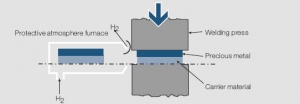
Beim Warmpressschweißen, dem klassischen Plattierverfahren, werden die zu verbindenden Werkstoffe in Blockform zu einem Schweißpaket zusammengestellt, auf ca. 800°C erwärmt und unter hohem Pressdruck verschweißt Figure 1. Dabei entsteht in der Berührungsfläche der beiden Werkstoffe eine unlösbare stoffschlüssige Verbindung entweder in fester Phase durch Diffusion der Reaktionspartner oder in flüssiger Phase mittels einer zwischengelegten Lotfolie bzw. durch Bildung eines AgCu-Eutektikums. Die Weiterverarbeitung des Werkstoffverbundes erfolgt durch Walzen mit entsprechenden Zwischenglühungen. Der Nachteil dieser Plattiertechnik liegt verfahrensbedingt in den kurzen Fertigungslängen.
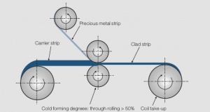
Beim Kaltwalzplattieren erfolgt die Verbindung zwischen Kontakt- und Trägerwerkstoff durch eine Kaltumformung > 50% in einem Stich Figure 2. Durch die starke plastische Verformung kommt es in der Grenzschicht zwischen den Plattierpartnern zu einer Kaltverschweißung. Um die Qualität der Schweißverbindung zu verbessern wird anschließend meist eine Diffusionsglühung durchgeführt. Dieses Fertigungsverfahren ist besonders zur Herstellung von plattiertem Halbzeug mit dünnen Kontaktauflagen (>2 μm) und großen Bandlängen (>100 m) geeignet.
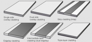
- Typische Ausführungsformen für Kontaktbimetalle Figure 3
- Kontaktwerkstoffe
Ag, Ag-alloys., Ag/Ni (SINIDUR), in Sonderfällen auch Ag/CdO (DODURIT CdO), Ag/SnO2 (SISTADOX), Ag/ZnO (DODURIT ZnO)
- Trägerwerkstoffe
Cu, CuSn, CuNiZn, CuNiSn, CuFe, CuBe u.a.
- Abmessungen Figure 4
Bei der Festlegung der Dicke der Edelmetalleinlage wird empfohlen, den Minimalwert anzugeben.
- Qualitätsmerkmale und Toleranzen
Festigkeitswerte und Maßtoleranzen von Kontaktbimetallen sind an die für Cu und Cu-Legierungen geltenden Normen EN 1652 und EN 1654 angelehnt. Bei der Vermaßung der Breite der Edelmetalleinlage wird empfohlen, von den für die jeweilige Anwendung erforderlichen Minimalwerten auszugehen. Die Vermaßung sollte stets von der Bandkante aus erfolgen..
Gelötete Halbzeuge (Toplay-Profile)
Das Toplay-Verfahren geht von einem flachen oder profilierten edelmetallhaltigen Kontaktband aus, das zusammen mit einem Hartlotstreifen und dem unedlen Trägerband einem Induktions-Lötautomaten zugeführt wird Figure 5. Dabei lässt sich eine gleichmäßige und zuverlässige Lötverbindung zwischen Kontaktauflage und Trägermaterial herstellen. Der so erzeugte Werkstoffverbund mit erhabener Edelmetallauflage ist nach dem Löten weich und wird anschließend auf profilierten Walzen nachverfestigt. Auf diese Weise können unterschiedliche Profilformen hergestellt werden.
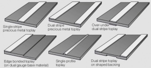
- Typische Ausführungsformen für Toplay-Profile Figure 6
- Kontaktwerkstoffe
Ag, AgNi 0,15 (ARGODUR), AgCu, AgCuNi (ARGODUR 27), Ag/Ni (SINIDUR),
Ag/CdO (DODURIT CdO), Ag/SnO2 (SISTADOX), Ag/ZnO (DODURIT ZnO)
- Trägerwerkstoffe
Cu, CuZn, CuSn u.a.
- Qualitätsmerkmale, Abmessungen und Toleranzen Figure 7
Festigkeitswerte und Maßtoleranzen von Toplay-Profilen sind angelehnt an die für Cu und Cu-Legierungen geltenden Normen EN 1652 und EN 1654.
Seam–Welded Contact Strip Materials (FDR–Profiles)
Seam–welding is the process by which the contact material in the form of a solid wire, narrow clad strip, or profile is attached to the carrier strip by overlapping or continuous weld pulses between rolling electrodes Figure 9. The weld joint is created by simultaneous effects of heat and pressure. Except for the very small actual weld joint area the original hardness of the carrier strip is maintained because of the limited short time of the heat supply. Therefore also spring-hard base materials can be used without loss of their mechanical strength. The use of clad contact pre-materials and profiles allows to minimize the use of the costly precious metal component tailored to the need for optimum reliability over the expected electrical life of the contact components.
- Typical configurations of seam–welded contact strips and stamped parts Figure 8
- Contact materials
Au-Alloys, Pd-Alloys, Ag, AgNi 0,15 (ARGODUR), AgCu, AgCuNi (ARGODUR 27), Ag/Ni (SINIDUR), Ag/CdO (DODURIT CdO), Ag/SnO2 (SISTADOX), Ag/ZnO (DODURIT ZnO)
- Carrier materials
Cu, CuSn, CuZn, CuNiZn, CuBe et al.
- Dimensions Figure 10
- Quality criteria and tolerances
Strength properties and dimensional tolerances of toplay profiles are derived from the standards DIN EN 1652 and DIN EN 1654 for Cu alloys..
Contact Profiles (Contact Weld Tapes)
Contact profiles span a broad range of dimensions. Width and thickness are typically between 0.8 – 8.0 mm and 0.2 – 3.0 mm resp. Special configurations, often defined as miniature-profiles or even micro–profiles can have a width < 2.0 mm.
Miniature–profiles are mostly composed of a contact-bimetal material with the contact material being a precious metal alloy or composite material clad, welded or coated by electroplating or vacuum-deposition (sputtered) onto a weldable base material. Since these profiles are attached to carrier strip materials usually by segment– or seam– welding to the base materials, materials with good welding properties such as nickel, copper-nickel, copper-tin, as well as copper-nickel-zinc alloys are used. The bottom surface of the profiles usually has formed weld rails or similar patterns to ensure a solid continuous metallurgical weld joint between the profile and the contact carrier.
Contact profiles in larger sizes are often used for switching devices in the low voltage technology. For these the contact layer mostly consists of arc erosion resistant materials such as silver–nickel, silver–metal oxides or the weld resistant silver– graphite. The brazable or weldable underside of the metal oxide or silver–graphite materials is usually pure silver with also quite often a thin layer of a phosphorous containing brazing alloy applied to aid the welding process.
- Typical configurations of multi-layer contact profiles Figure 11
- Contact materials
Au-Alloys, Pd-Alloys, Ag-Alloys, Ag/Ni (SINIDUR), Ag/CdO (DODURIT CdO), Ag/SnO2 (SISTADOX), Ag/ZnO (DODURIT ZnO)
- Carrier materials
(weldable substrate material for multi-layer materials) Cu, Ni, CuNiFe, CuNiZn, CuSn, CuNiSn, NiCuFe
- Brazing alloy
L-Ag15P
- Quality criteria
Beause of the variety of configurations of contact profiles usually the quality issues are separately agreed upon between the manufacturer and the user.
- Dimensions and tolerances Figure 12
The thickness of the Au top-layer, which is sputtered for example, is between 0.2 and 5 μm, depending on the requirements. Tolerance of thickness is about ± 10%.
