Contact Spring Calculations
6.4.7 Contact Spring Calculations
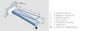
Fig. 6.20:
One side fixed contact bending spring
L = Length of spring
E = Modulus of elasticity
B = Width of spring
F = Spring force
D = Thickness of spring
x = Deflection
max = maximum bending force
The influence of the dimensions can be illustrated best by using the single side fixed beam model (Fig. 6.20). For small deflections the following equation is valid:
where J is the momentum of inertia of the rectangular cross section of the beam
For springs with a circular cross-sectional area the momentum of inertia is
J=BD4/64 D= Durchmesser
To avoid plastic deformation of the spring the max bending force σ cannot be max exceeded
Fmax= 3 x E x D xmax 2L²
The stress limit is defined through the fatigue limit and the 0.2% elongation limit resp.
xmax= 2 x L ² Rp0,2 3 x D x E
and/or
Fmax= B x D ² Rp0,2 6L
- Special Spring Shapes
- Triangular spring
Deflection x= L³ F 2 x E x J
= x L³ D³ 6 x F E x B
Max. bending force Fmax= 1 8 x F x L B x D²
- Trapezoidal spring
Deflection x= x L³ E x J F (2 + B /B )
x= x L³ E x B x D³ 12 x F (2 + B /B ) min ma
Max. bending force
Fmax= 1 8 x F x L (2 + B /B ) x B x D² min max max

