Gold Based Materials
Pure Gold is besides Platinum the chemically most stable of all precious metals. In its pure form it is not very suitable for use as a contact material in electromechanical devices because of its tendency to stick and cold-weld at even low contact forces. In addition it is not hard or strong enough to resist mechanical wear and exhibits high materials losses under electrical arcing loads. This limits its use in form of thin electroplated or vacuum deposited layers.
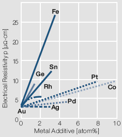
For most electrical contact applications gold alloys are used. Depending on the alloying metal the melting is performed either under in a reducing atmosphere or in a vacuum. The choice of alloying metals depends on the intended use of the resulting contact material. The binary Au alloys with typically <10 wt% of other precious metals such as Pt, Pd, or Ag or non-precious metals like Ni, Co, and Cu are the more commonly used ones (Table 2.2). On one hand these alloy additions improve the mechanical strength and electrical switching properties but on the other hand reduce the electrical conductivity and chemical corrosion resistance (Fig. 2.2) to varying degrees.
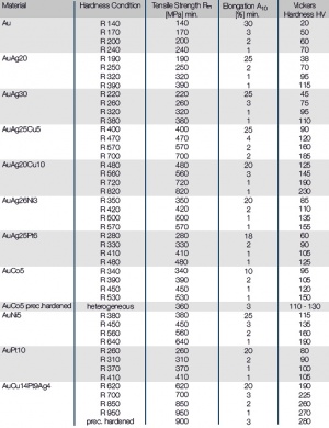
Under the aspect of reducing the gold content ternary alloys with a gold content of approximately 70 wt% and additions of Ag and Cu or Ag and Ni resp., for example AuAg25Cu5 or AuAg20Cu10 are used which exhibit for many applications good mechanical stability while at the same time have sufficient resistance against the formation of corrosion layers (Table 2.3).
Tab.2.3: Mechanical Properties of Gold and Gold-Alloys
| Material | Hardness Condition | Tensile Strength Rm [MPa] min. | Elongation A10 [%] min. | Vickers Hardness HV |
|---|---|---|---|---|
| Au | R 140 R 170 R 200 R 240 |
140
170 200 240 |
30
3 2 1 |
20
50 60 70 |
| Copper and copper alloys in plate, sheet, strip, and discs for general applications | ||||
| DIN EN 1654 | Copper and copper alloys for springs and connectors | |||
| DIN EN 1758 | Copper and copper alloys in strip form for system component carriers | |||
| ASTM B 103/B103M-10 | Spec. for Phosphor Bronce Plate, Sheet, Strip, and Rolled Bar | |||
| ASTM B 36/B36M-95 | Spec. for Brass Plate, Sheet, Strip, and Rolled Bar | |||
| ASTM B 122/B122M-08 | Spec. for CuNiSn-, CuNiZn-, and CuNi-Alloy | |||
| ASTM B 465-09 | Spec. for Copper-Iron-Alloy Plate, Sheet, and Strip | |||
| ASTM B 194-08 | Standard Spec. for CuBe-Alloy Plate, Sheet, Strip and Rolled Bar | |||
| ASTM B 534-07 | Sec. for CuCoBe-Alloy and CuNiBe-Alloy Plate, Sheet, Strip, and Rolled Bar |
Other ternary alloys based on the AuAg system are AuAg26Ni3 and AuAg25Pt6. These alloys are mechanically similar to the AuAgCu alloys but have significantly higher oxidation resistance at elevated temperatures (Table 2.4).
Table 2.4: Contact and Switching Properties of Gold and Gold Alloys
Material | Properties | |
Au | Highest corrosion resistance, low hardness | High electr. conductivity, strong tendency to cold welding |
AuAg8 | High corrosion resistance, low thermo e.m.f. | Low contact resistance |
AuPt10 AuPd5 | Very high corrosion resistance | High hardness |
AuAg10 - 30 | Mostly corrosion resistant | Higher hardness |
AuNi5 AuCo5 | High corrosion resistance, low tendency to material transfer | High hardness |
AuAg25Pt6 | High corrosion resistance, low contact resistance | High hardness |
AuAg26Ni3 AuAg25Cu5 AuAg20Cu10 | Limited corrosion resistance | High hardness |
AuPd40 AuPd35Ag10 AuCu14Pt9Ag4 | High corrosion resistance | High hardness and mechanical wear resistance |
Caused by higher gold prices over the past years the development of alloys with further reduced gold content had a high priority. The starting point has been the AuPd system which has continuous solubility of the two components. Besides the binary alloy of AuPd40 and the ternary one AuPd35Ag9 other multiple component alloys were developed. These alloys typically have < 50 wt% Au and often can be solution hardened in order to obtain even higher hardness and tensile strength. They are mostly used in sliding contact applications.
Gold alloys are used in the form of welded wire or profile (also called weldtapes), segments, contact rivets, and stampings produced from clad strip materials. The selection of the bonding process is based on the cost for the joining process, and most importantly on the economical aspect of using the least possible amount of the expensive precious metal component.
Besides being used as switching contacts in relays and pushbuttons, gold alloys are also applied in the design of connectors as well as sliding contacts for potentiometers, sensors, slip rings, and brushes in miniature DC motors (Table 2.5).
Table 2.5: Application Examples and Forms of Gold and Gold Alloys
Material | Application Examples | Form of Application |
Pure Gold (electroplated) | Corrosion protection layer for contact parts, stationary contacts, bonding surfaces | Electroplated coatings, bond surface layers |
Hard Gold (sputtered) | Contact parts for connectors and switches, sliding contact tracks, bonding surfaces | Electroplated coatings on contact rivets and stamped parts |
Hard Gold (sputtered) | Contacts in switches and relays for low loads, electronic signal relays | Contact surface layer on miniature profiles (weld tapes) |
AuAg8 | Dry circuit switching contacts, electronic signal relays | Contact rivets, welded contact parts |
AuAg20 | Switching contacts for low loads, electronic signal relays | Contact rivets, welded contact parts |
AuAg25Cu5 AuAg25Cu10 AuAg26Ni3 | Contact parts for connectors, switches and relays | Claddings on Cu alloys, contact rivets, contact layer on micro profiles (weld tapes) |
AuNi5 AuCo5 (heterogen) | Contacts in switches and relays for low and medium loads, material transfer resistant contacts | Contact rivets, welded contact parts, contact layer on miniature profiles (weld tapes) |
AuPt10 AuAg25Pt6 | Contacts for highest chemical corrosion resistance in switches and relays | Contact rivets, contact layer on micro profiles (weld tapes) |
AuCu14Pt9Ag4 | Sliding contacts for measurement data transfer | Wire-formed parts |
Table 2.1: Commonly Used Grades of Gold
Designation | Composition Au (min. content) | Impurites ppm | Remarks on forms and application |
Electronic Glod Gold | 99.999 | Cu < 3 Ag < 3 Ca < 1 Mg <1 Fe < 1 | Wires, strips, alloying metal for semiconductors, electronic components |
Pure Gold | 99.995 | Cu < 10 Ag < 15 Ca < 20 Mg < 10 Fe < 3 Si < 10 Pb < 20 | Granulate for high purity alloys, strips, tubing, profiles |
Ingot Grade-Gold | 99.95 | Cu < 100 Ag < 150 Ca < 50 Mg < 50 Fe < 30 Si < 10 | Alloys, commonly used grade |
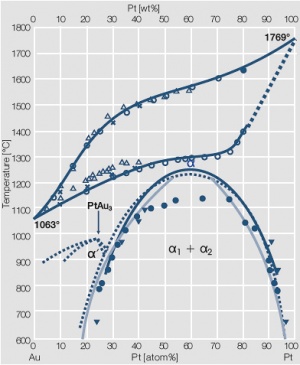
Fig. 2.3: Phase diagram of goldplatinum
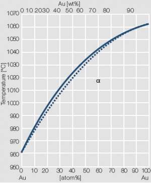
Fig. 2.4: Phase diagram of gold-silver
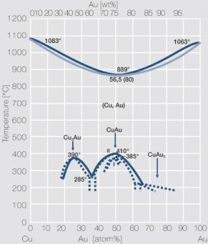
Fig. 2.5: Phase diagram of gold-copper
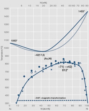
Fig. 2.6: Phase diagram of gold-nickel
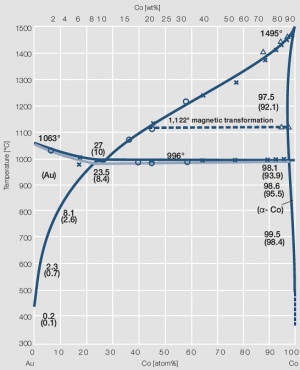
Fig. 2.7: Phase diagram of gold-cobalt
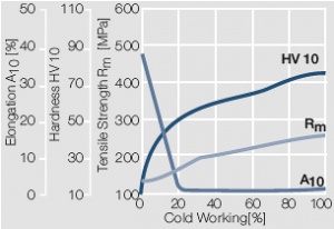
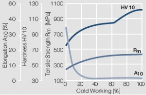
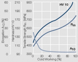
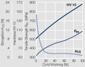
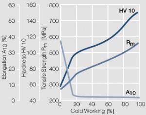
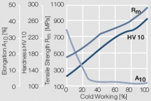
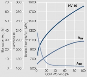
Fig. 2.8: Strain hardening of Au by cold working
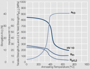
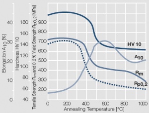
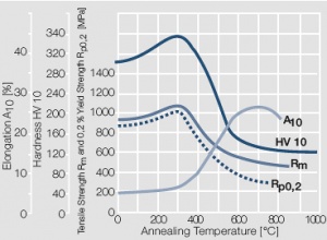
Fig. 2.9: Softening of Au after annealing for 0.5 hrs after 80% cold working
Fig. 2.10: Strain hardening of AuPt10 by cold working
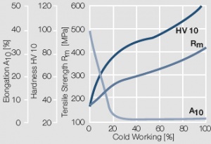
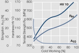
Fig. 2.11: Strain hardening of AuAg20 by cold working
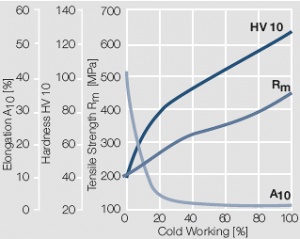
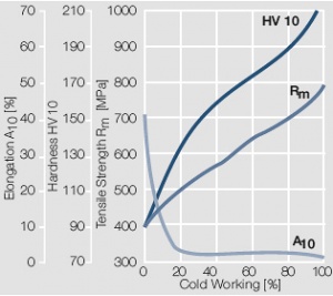
Fig. 2.12: Strain hardening of AuAg30 by cold working
Fig. 2.13: Strain hardening of AuNi5 by cold working
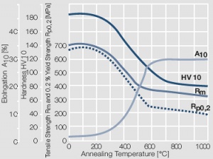
Fig. 2.14: Softening of AuNi5 after annealing for 0.5 hrs after 80% cold working
Fig. 2.15: Strain hardening of AuCo5 by cold working
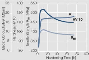
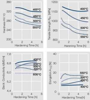
Fig. 2.16: Precipitation hardening of AuCo5 at 400°C hardening temperature
Fig. 2.17: Strain hardening of AuAg25Pt6 by cold working
Fig. 2.18: Strain hardening of AuAg26Ni3 by cold working
Fig. 2.19: Softening of AuAg26Ni3 after annealing for 0.5 hrs after 80% cold working
Fig. 2.20: Strain hardening of AuAg25Cu5 by cold working
Fig. 2.21: Strain hardening of AuAg20Cu10 by cold working
Fig. 2.22: Softening of AuAg20Cu10 after annealing for 0.5 hrs after 80% cold working
Fig. 2.23: Strain hardening of AuCu14Pt9Ag4 by cold working
Fig. 2.24: Precipitation hardening of AuCu14Pt9Ag4 at different hardening temperatures after 50% cold working

