Difference between revisions of "Testing of Contact Surface Layers"
Doduco Admin (talk | contribs) |
Doduco Admin (talk | contribs) (→Layer Thickness) |
||
| Line 11: | Line 11: | ||
The primary requirement on an electroplated deposit is its thickness, since a series of other properties such as porosity, hardness and ductility, are depending on the layer thickness. A widely used method for thickness measurement is the microscopical evaluation of a mounted micro | The primary requirement on an electroplated deposit is its thickness, since a series of other properties such as porosity, hardness and ductility, are depending on the layer thickness. A widely used method for thickness measurement is the microscopical evaluation of a mounted micro | ||
section. Because of optical resolution limits however, layer thicknesses below 0.5 μm cannot be measured with sufficient accuracy. For low coating | section. Because of optical resolution limits however, layer thicknesses below 0.5 μm cannot be measured with sufficient accuracy. For low coating | ||
| − | thicknesses the x-ray fluorescence method is used, which often is integrated for quality assurance into the manufacturing process, for example in selective | + | thicknesses the x-ray fluorescence method is used, which often is integrated for quality assurance into the manufacturing process, for example in selective reel-to- reel electroplating plating lines. In this process, the returned characteristic x-ray impulses of the coating material and the substrate, generated by the primary x-rays, are detected and counted and then converted into material thickness by a computerized indicator or recording and control unit. |
====<!--13.2.1.2-->Porosity==== | ====<!--13.2.1.2-->Porosity==== | ||
Revision as of 12:59, 9 January 2023
Testing of Contact Surface Layers
For applications at low switching loads, contact layers with thicknesses in the range of just a few micrometers are widely used. For testing such thin layers, the actual coating properties must be distinguished from the functional properties. Coating properties include, besides others, porosity, hardness and ductility. Depending on the application, the most important function properties are for example frictional wear, contact resistance, material transfer or contact welding behavior. Besides these, other technological properties such as adhesion strength and solderability, may also be of importance for special applications like those for electronic components.
The following descriptions are mainly applicable to electroplated contact coatings, which are of the most economical importance in contact applications. They also apply however in similar form to surface layers, which have been created by mechanical cladding or by sputtering.
Surface Layer Properties
Layer Thickness
The primary requirement on an electroplated deposit is its thickness, since a series of other properties such as porosity, hardness and ductility, are depending on the layer thickness. A widely used method for thickness measurement is the microscopical evaluation of a mounted micro section. Because of optical resolution limits however, layer thicknesses below 0.5 μm cannot be measured with sufficient accuracy. For low coating thicknesses the x-ray fluorescence method is used, which often is integrated for quality assurance into the manufacturing process, for example in selective reel-to- reel electroplating plating lines. In this process, the returned characteristic x-ray impulses of the coating material and the substrate, generated by the primary x-rays, are detected and counted and then converted into material thickness by a computerized indicator or recording and control unit.
Porosity
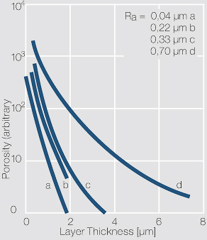
Pores are surface defects which may have multiple causes. These include roughness and defects in the substrate layer or material, such as grooves or scratch marks, as well as cracks in the base material which may have been generated by bend stresses or mechanical wear (Figure 1).
At the foot points of the pores, the substrate material is exposed to the surrounding atmosphere. This can cause corrosion products to rise through the pores to the contact surface, expand there further and thus lead to increased contact resistance. The allowable number of pores in gold layers, for example for connectors, mainly depends on the concentration of corrosive gases in the intended working environment.
Most methods of porosity testing are based on detecting the substrate material which is transferred to the surface during an electrochemical treatment process. For testing of gold and palladium coatings on nickel containing substrates, the dimethyl-glyoxin test for detecting the nickel has been a proven method. The electrochemical methods are mostly working on a electrographic or electrolytic basis.
In the electrographic test, a strip of filter material saturated with an electrolyte or a gelatin foil is pressed onto the sample. After the application of an electrical field and current, the reaction products are made visible by chemical indicators.
During the electrolytic test, a sample is immersed into an electrolyte, containing an indicator solution. After passing electrical current, the pores are visible as colored spots.
Frequently a SO test at higher concentrations (100 ppm) and high humidity (2 levels, 95% RH at 40°C) is used. One advantage of this method is, that the severity level can be increased easily by varying the concentration of SO2. Besides these, other corrosive gas mixtures of H2S, SO2, and NO2 are used in porosity tests (i.e. tests according to ASTM B735 and B 799).
Hardness
The hardness of electroplated surface coatings depends on their deposition parameters and therefore on the structure and concentration of incorporated substances. The hardness measurement is however not a true indicator of the mechanical properties such as frictional wear characteristics like for clad meltmetallurgically produced layers. This is caused by their fundamentally different structure compared to alloys. Brittleness and internal stresses also have an influence on the hardness.
Usually hardness is measured in Europe and Asia applying the Vickers scale (DIN EN ISO 6507-1) for which an indenter of a symmetrical diamond shape is used. For thin layers, the micro-hardness is measured in a metallographic crosssectional mount (DIN ISO 416).
In the US, the hardness values are often reported by values of the Knoop scale. This method uses a asymmetrical diamond indenter on the layer, producing a rhombic indentation picture. Values obtained by both methods are comparable but cannot be converted into each other easily.
During hardness measurements, the indentation depth should not exceed 10% of the layer thickness. Depth of up to 30% can be accepted only, if the hardness values of the layer and substrate are in a similar range. For layers of pure metals, the hardness of the base material can influence the one for the coating in the immediate boundary area. A decrease in hardness can then be observed towards the layer's surface.
Ductility
The ductility indicates how much a coating layer can be plastically deformed without cracking. Therefore it is an important measure for the quality of electroplated coatings. If the ductility is too low, cracks can develop in the layer. This crack formation can occur due to internal stresses right after the deposition or develop from mechanical stressing during subsequent mechanical deformation.
To evaluate the ductility of gold layers, a bending test according to DIN 50 153 is usually employed. For certain applications, the testing method is agreed upon between the coating manufacturer and the user. After bending the test sample over a pre-defined radius, the surface layer in the bend area is examined microscopically. The detection of cracks or even delaminating is an indication of insufficient ductility.
Functional Properties
Frictional Wear
For contact parts which are subjected to frictional sliding between each other, such as, for example, connector or sliding contact parts, frictional wear is the determining factor for contact life and reliability. In general, it is assumed that harder surfaces are more wear resistant. This usually is true for molten alloys, but not necessarily the fact for electroplated surface layers. As an example, low-carat molten AuCuCd layers exhibit, despite a high hardness (HV 350), a higher mechanical wear than high-carat electroplated hard gold coatings (HV 120).
In the latter, the incorporated carbon content acts as a lubricant, reducing wear significantly. After these tests, additional tests are performed, e.g. on real connectors, which then take into account the actual design features in the contact area of the connector..
Contact Resistance
The contact resistance is the most important functional property determining the reliability of a contact layer.
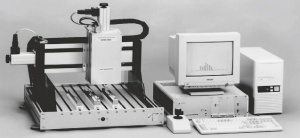
For the measurement of the contact resistance, commercially available test instruments with applicable data analysis programs are used (Figure 2). In a pre-set program, the surface of a contact layer is scanned and probed. Most frequently, a freshly cleaned contact rivet with a hard gold coated contact rivet is used as the probing contact.
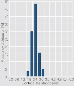
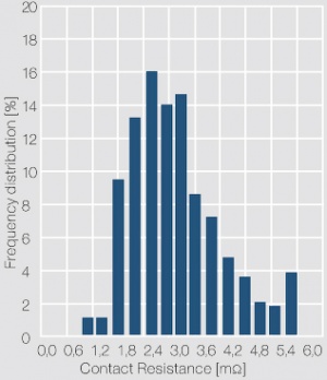
The measuring voltage and current are usually in the range of < 20 mV and 10 mA (DC or 1 kHz AC). The contact force is selected as 2, 5 or 10 cN, depending on the application of the contacts. A histogram of the individual resistance data is usually used to show the frequency distribution of the data and serves as an indicator for the cleanliness of the contact surface. As shown in (Figure 3) for a gold contact layer, a narrow scatter range and symmetrical distribution of the contact resistance values is typical for clean and tarnish film free contact surface. In case of the contact surface being partially or totally covered with a tarnish film, characteristic asymmetrical contact resistance distributions are evident (Figure 4). While the contact resistance distribution can show the presence of tarnish films, only surface analytical methods can clarify their type and composition.
Technological Properties
Adhesion Strength
Good adhesion of the electroplated layer on the substrate is mandatory for the reliable function of a contact system. The adhesion strength between the electroplated surface coating and the substrate depends on many factors, such as the surface roughness of the carrier metal, the surface preparation, thermal expansion properties, ductility and others. A difference in formability of layer and substrate metal can easily lead to separation of the coating layer. Rapid temperature changes can also lead to delaminating, if the thermal coefficients of expansion of the coating and the substrate differ substantially. A prerequisite for good adhesion is the careful surface preparation prior to the actual electroplating, which is usually integrated into the electroplating process equipment.
There is no non-destructive test method which can be applied under practical use conditions. The methods used are mechanical tests, such as a fold and bend test or the wrap test. Often also an adhesive strip test according to DIN IEC 326 Part 2 is used. A transparent adhesive tape is applied to the electroplated surface and removed again after 10s by a uniform pulling action.
During this removal, the coating layer is not allowed to come off the substrate, which means no substrate material is allowed to become visibly exposed.
Quite often temperature tests are also used to judge the adhesion strength. For these, the samples are exposed to elevated temperatures between 120 and 400°C over a defined time period (5 to 60 min). At insufficient bonding strength, bubbles are becoming visible and delaminating may occur.
Solderabilty
In this context, soldering is defined as using low temperature tin or tin alloys. A freuquently used method to determine the solderability is the immersion test. The coated material is inserted into a bath of the liquid solder and tinned for about 5 s. After this exposure 95% of the surface immersed must be wetted with the solder. One of the requirements for complete wetting also is, that the interface area between the substrate metal and the coating layer is not interrupted by oxides or other foreign substances.
Gold is known to be well solderable, however problems can occur when soldering onto thin gold layers. Since the gold quickly dissolves in the soldering alloy, the viscosity of the liquid solder is increased and can lead to reduced wetting. Gold and tin also form intermetallic compound phases which lead to embrittlement and thus reduce the mechanical strength of the solder bond. In addition non-precious alloying components or co-deposited carbon can be problematic for good solderability.
Bondability
The wire bonding – a welding process of fine wires onto flat semiconductors and metal surfaces – was developed for contacting semiconductor components. (Chapter Applications for Bonding Technologies) Depending on the application, the reliability of the bond connections over extended time periods and under difficult environmental conditions is of great importance. The quality of such connections can only be evaluated in destructive pull or shear tests.
- Pull Test
During the pull test, a hook is inserted into the bond wire loop and the pull force is slowly increased to an amount that destroys the connection. During this test, the weakest spot of the bond loop is determined. The actual delaminating between bond wire and substrate is deemed the most serious defect. The transition between bond spot and wire is a weak point because of the high deformation stresses exerted onto the wire, which can also lead to break. A break in the actual wire is the most desirable result condition during the pull test.
Typical rupture pull forces measured, are in the range of the rupture strength of the bond wire (i.e. 10 – 15 cN for a 25 μm diameter Au wire) and depend on the geometry of the loop.
- Shear Test
The shear test is used as an alternative to the pull test. A shear force is excerted onto the bond area. Separation then occurs between the bond layer and bond wire or for a good bond connection within the bond wire.
- Aging Test
A higher difficulty for testing occurs if the initial bond test results from pulling or shearing were good at high forces, but later the bond connections show early failures due to aging.
One of the most severe tests is an exposure at a humidity level of 85% RH and at 85°C. At higher porosity levels in the coating, the high humidity can lead to corrosion effects on the substrate material from corrosive gases in the atmosphere. For the most severe requirements, a simulation test at 85°C and 85% RH is performed over a 500 h exposure time period.


