Difference between revisions of "Trägerwerkstoffe"
Teitscheid (talk | contribs) (temp edit) |
Teitscheid (talk | contribs) (temp edit) |
||
| Line 550: | Line 550: | ||
siehe Artikel: [[Sonstige_naturharte_Kupfer-Legierungen| Sonstige naturharte Kupfer-Legierungen]] | siehe Artikel: [[Sonstige_naturharte_Kupfer-Legierungen| Sonstige naturharte Kupfer-Legierungen]] | ||
| − | ===<!--5.1.6--> | + | ===<!--5.1.6-->Aushärtbare Kupfer-Legierungen=== |
| − | + | Neben den naturharten Kupferwerkstoffen spielen aushärtbare Kupferlegierungen | |
| + | als Trägerwerkstoffe für elektrische Kontakte eine wichtige Rolle. | ||
| + | Bei den aushärtbaren Legierungen können durch eine geeignete Wärmebehandlung | ||
| + | fein verteilte Ausscheidungen einer zweiten Phase erzeugt werden, | ||
| + | die die Festigkeit des Werkstoffes deutlich erhöhen. | ||
| − | siehe Artikel: [[ | + | siehe Artikel: [[Aushärtbare_Kupfer-Legierungen| Aushärtbare Kupfer-Legierungen]] |
| − | ===<!--5.1.7--> | + | ===<!--5.1.7-->Kenngrößen zur Bewertung der Eigenschaften von Kupfer-Legierungen=== |
| − | + | Für federnd beanspruchte Bauelemente stellen neben Festigkeit und elektrischer | |
| + | Leitfähigkeit vor allem die typischen Federeigenschaften, wie Federbiegegrenze | ||
| + | und Biegewechselfestigkeit sowie die Biegbarkeit wichtige Kenngrößen | ||
| + | dar. Bei höherer thermischer Beanspruchung wird das Verhalten der | ||
| + | Federwerkstoffe durch Entfestigung und Relaxation bestimmt. Im folgenden | ||
| + | sollen diese Kenngrößen kurz beschrieben werden. | ||
| − | siehe Artikel: [[ | + | siehe Artikel: [[Kenngrößen_zur_Bewertung_der_Eigenschaften_von_Kupfer-Legierungen| Kenngrößen zur Bewertung der Eigenschaften von Kupfer-Legierungen]] |
===<!--5.1.8-->Selection Criteria for Copper-Based Materials=== | ===<!--5.1.8-->Selection Criteria for Copper-Based Materials=== | ||
Revision as of 00:17, 20 September 2014
Die Zuverlässigkeit und Lebensdauer von Kontaktsystemen in Schaltgeräten sowie elektromechanischen und elektronischen Bauelementen hängen häufig nicht allein vom eingesetzten Kontaktwerkstoff ab. Auch die Wahl des geeigneten Trägerwerkstoffes spielt eine entscheidende Rolle.
Als Trägermaterialien haben Werkstoffe auf Kupferbasis die größte Bedeutung. Je nach Anwendung kommen auch Werkstoffe auf Nickelbasis oder Mehrschicht- Verbundwerkstoffe, z.B. Thermobimetalle zum Einsatz. Für spezielle Anwendungen in der Mittel- und Hochspannungstechnik sowie für Kontaktfedern und Schnappscheiben in der Informationstechnik werden Werkstoffe auf Eisenbasis berücksichtigt, die aber im Rahmen dieses Datenbuches nicht behandelt werden.
Die Anforderungen, die an die Trägerwerkstoffe gestellt werden, sind entsprechend ihres unterschiedlichen Einsatzes vielfältig. So werden von Kupferwerkstoffen, neben einer hohen elektrischen und thermischen Leitfähigkeit, gute Festigkeitseigenschaften auch bei erhöhten Temperaturen sowie eine ausreichend hohe Korrosionsbeständigkeit verlangt. Werden die Trägerwerkstoffe als Kontaktfedern eingesetzt, so muss der Werkstoff noch zusätzlich gute Federeigenschaften aufweisen. Daneben sind je nach Fertigungsprozess auch eine Reihe technologischer Eigenschaften, wie gute Warm- und Kaltumformbarkeit, spanende Formbarkeit, Stanzbarkeit, Schweiß- und Lötbarkeit sowie Galvanisierbarkeit, zu nennen.
Contents
- 1 Kupfer und Kupfer-Legierungen
- 1.1 Übersicht über Normen
- 1.2 Reines Kupfer
- 1.3 Niedriglegierte Kupfer-Werkstoffe
- 1.4 Naturharte Kupfer-Legierungen
- 1.5 Sonstige naturharte Kupfer-Legierungen
- 1.6 Aushärtbare Kupfer-Legierungen
- 1.7 Kenngrößen zur Bewertung der Eigenschaften von Kupfer-Legierungen
- 1.8 Selection Criteria for Copper-Based Materials
- 2 Nickel and Nickel Alloys
- 3 Triple-Layer Carrier Materials
- 4 Thermostatic Bimetals
- 5 Kommentare
- 6 Referenzen
Kupfer und Kupfer-Legierungen
Übersicht über Normen
Werkstoffe aus Kupfer und Kupferlegierungen, die für den Einsatz in der Elektrotechnik und Elektronik vorgesehen sind, werden i.d.R. in Normen festgelegt. Nach DIN genormte Werkstoffe werden durch Kurzzeichen und Werkstoffnummer beschrieben. In den europäischen Normen (EN) sind die Werkstoffe den aus ihnen hergestellten Produkten zugeordnet und ebenfalls durch Kurzzeichen und Werkstoffnummer gekennzeichnet. Zum Vergleich werden auch die Werkstoffbezeichnungen nach UNS (Unified Numbering System (USA)) angeführt Table 1.
Die für den Bereich elektrischer Kontakte wichtigen EN-Normen sowie entsprechende ASTM (American Society for Testing and Materials)-Normen für Walzflacherzeugnisse aus Kupfer und Kupferlegierungen sind:
| Normbezeichnung | Beschreibung |
|---|---|
| DIN EN 1652 | Kupfer und Kupferlegierungen in Platten, Blechen, Bändern, Streifen und Ronden zur allgemeinen Verwendung |
| DIN EN 1654 | Kupfer und Kupferlegierungen für Federn und Steckverbinder |
| DIN EN 1758 | Kupfer und Kupferlegierungen als Bänder für Systemträger |
| ASTM B 103/B103M-10 | Spec. for Phosphor Bronce Plate, Sheet, Strip, and Rolled Bar |
| ASTM B 36/B36M-95 | Spec. for Brass Plate, Sheet, Strip, and Rolled Bar |
| ASTM B 122/B122M-08 | Spec. for CuNiSn-, CuNiZn-, and CuNi-Alloy |
| ASTM B 465-09 | Spec. for Copper-Iron-Alloy Plate, Sheet, and Strip |
| ASTM B 194-08 | Standard Spec. for CuBe-Alloy Plate, Sheet, Strip and Rolled Bar |
| ASTM B 534-07 | Sec. for CuCoBe-Alloy and CuNiBe-Alloy Plate, Sheet, Strip, and Rolled Bar |
Die oben angeführten EN-Normen ersetzen teilweise oder vollständig die DIN-Normen: DIN 1777, DIN 17670, DIN 1751, DIN 1791
Reines Kupfer
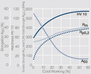
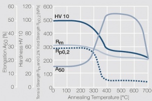
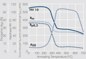
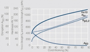
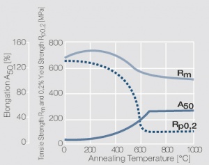
Kupfer wird in der Elektrotechnik vor allem wegen seiner hohen elektrischen ) Leitfähigkeit[1] eingesetzt, die mit 58 MS/m nur wenig unter der des Silbers liegt. Weitere Vorzüge des Kupfers sind seine hohe Wärmeleitfähigkeit, Korrosionsbeständigkeit und seine gute Umformbarkeit. Das Verfestigungsverhalten von Cu-ETP ist in Figure 1 dargestellt. Die durch Kaltumformung erreichte Verfestigung kann durch eine nachfolgende Wärmebehandlung wieder aufgehoben werden. Dabei hängt das Erweichungsverhalten stark vom Zustand der Kaltumformung ab (Figure 2 und Figure 3).
Die Reinheit des für elektrische Zwecke verwendeten technisch reinen, unlegierten Kupfers liegt je nach Kupfersorte bei > 99,90 bzw. 99,95 Massen-%. Die unterteilt in sauerstoffhaltige, sauerstofffreie und mit Phosphor desoxidierten Kupfersorten sind in DIN EN 1652 festgelegt (Table 1 und Table 2). Die physikalischen und mechanischen Eigenschaften einiger Reinkupfersorten sind in Table 3 and Table 4 aufgeführt. Demnach sind Cu-ETP, Cu-OF und Cu-HCP Kupfersorten, bei denen bestimmte Mindestwerte für die elektrische Leitfähigkeit garantiert werden.
Cu-ETP eignet sich wegen seines Sauerstoffanteils nicht zum Schweißen oder Hartlöten in reduzierender Atmosphäre (Gefahr der Wasserstoffkrankheit).
Cu-HCP, Cu-DLP und Cu-DHP sind sauerstofffreie, mit unterschiedlichen Phosphorgehalten desoxidierte Kupfersorten. Mit zunehmendem Phosphorgehalt sinkt die elektrische Leitfähigkeit. Cu-OF ist sowohl frei von Sauerstoff als auch von Desoxidationsmittel.
| Werkstoffbezeichnung EN-Kurzzeichen | EN-Nummer | DIN-Kurzzeichen | DIN-Nummer | UNS |
|---|---|---|---|---|
| Cu-ETP | CW004A | E-Cu 58 | 2.0065 | C11000 |
| Cu-OF | CW008A | OF-Cu | 2.0040 | C10200 |
| Cu-HCP | CW021A | SE-Cu | 2.0070 | C10300 |
| Cu-DLP | CW023A | SW-Cu | 2.0076 | C12000 |
| Cu-DHP | CW024A | F-Cu | 2.0090 | C12200 |
| Werkstoff | Zusammensetzung Massenanteile [%] | |||||
|---|---|---|---|---|---|---|
| EN Kurzzeichen | Cu | Bi | O | P | Pb | Sonstige |
| Cu-ETP | >99.90 | bis 0.0005 | bis 0.040 | bis 0.005 | bis 0.03 | |
| Cu-OF | >99.95 | bis 0.0005 | bis 0.005 | bis 0.03 | ||
| Cu-HCP | >99.90 | ca. 0.003 | ||||
| Cu-DLP | >99.90 | bis 0.005 | 0.005-0.013 | bis 0.005 | bis 0.03 | |
| Cu-DHP | >99.90 | 0.015-0.040 | ||||
Werkstoffbezeichnung | Dichte | Elektr. Leitfähigkeit | Elektr. Widerstand | Wärmeleitfähigkei |
Coeff. of Lin. Ausdehnungskoeffizient |
E-Moduls of Erweichungstemp. (ca.10% Festigkeitsabfall) | Schmelztemperatur | ||
|---|---|---|---|---|---|---|---|---|---|
EN-Kurzzeichen |
[g/cm³] | [MS/m] | [% IACS] | [μΩ· cm] | [W/(m· K)] | [10-6/K] | [GPa] | [°C] | [°C] |
Cu-ETP | 8.94 |
≥58 | 100 | 1.72 | 390 | 17.7 | 127 | ca. 220 | 1083 |
Cu-OF | 8.94 | ≥58 | 100 | 1.72 | 394 | 17.7 | 127 | ca. 220 | 1083 |
Cu-HCP | 8.94 | ≥54 | 93 | 1.85 | 380 | 17.7 | 127 | ca. 220 | 1083 |
Cu-DLP | 8.94 | 52 | 90 | 1.92 | 350 | 17.7 | 132 | ca. 220 | 1083 |
Cu-DHP | 8.94 | ≥46 | 80 | 2.17 | 310 | 17.6 | 132 | ca. 220 | 1083 |
Werkstoff | Zustand | Zugfestigkeit Rm [MPa] | 0,2% Dehngrenze Rp0,2 [MPa] | Bruchdehnung A50 [ %] | Härte HV |
|---|---|---|---|---|---|
|
Cu-ETP Cu-OF Cu-HCP Cu-DLP Cu-DHP |
R220 | 220 - 260 | ≤140 | ≥33 | 40 - 65 |
| R240 | 240 - 300 | ≥180 | ≥8 | 65 - 95 | |
| R290 | 290 - 360 | ≥250 | ≥4 | 90 - 110 | |
| R360 | ≥360 | ≥320 | ≥2 | ≥110 |
Figure 1 Verfestigungsverhalten von Cu-ETP
Figure 2 Erweichungsverhalten von Cu-ETP nach 3h Glühdauer und einer Kaltumformung von 25%
Figure 3 Erweichungsverhalten von Cu-ETP nach 3h Glühdauer und einer Kaltumformung von 50%
Niedriglegierte Kupfer-Werkstoffe
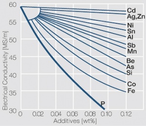
Die niedriglegierten Kupferwerkstoffe kommen in ihren Eigenschaften dem reinen Kupfer am nächsten. Durch gezielte Zugabe kleiner Mengen von Legierungselementen gelingt es, die Festigkeit und vor allem die Erweichungstemperatur des Kupfers zu erhöhen, wobei die elektrische Leitfähigkeit nur wenig verringert wird (Figure 4). Als Legierungselemente kommen z.B. Silber, Eisen, Zinn, Zink, Nickel, Chrom, Zirkon, Silizium und Titan zum Einsatz. Der Anteil der zulegierten Komponente liegt meist deutlich unter 3 Massen-%. Zu dieser Werkstoffgruppe sind sowohl mischkristall- als auch ausscheidungshärtende Legierungen zu zählen. Auf die aushärtbaren Kupfer-Beryllium- und Kupfer-Chrom-Zirkon-Werkstoffe wird später eingegangen.
Aus der großen Zahl der angebotenen niedriglegierten Kupferwerkstoffe können hier nur wenige herausgegriffen und ihre Eigenschaften aufgelistet werden (Table 5 und Table 6). Einige dieser Werkstoffe sind nicht in der EN enthalten.
Die niedriglegierten Kupferwerkstoffe CuAg0,1 und CuCd1 kommen vor allem als Fahrdrähte von Oberleitungen zum Einsatz, wo sie Dauerbelastungen bei erhöhten Temperaturen ohne Erweichung standhalten müssen.
Die Werkstoffe CuFe0,1 und CuSn0,15 zeichnen sich durch eine hohe elektrische Leitfähigkeit aus. Die Festigkeitswerte beider Werkstoffe sind zwar verhältnismäßig niedrig, bleiben jedoch bei kurzzeitiger Wämeeinwirkung bis ca. 400°C nahezu unverändert. Sie werden als Systemträger für Halbleiterbauelemente aber auch als Trägerteile für Festkontakte in Schaltgeräten der Energietechnik verwendet.
CuFe2P ist ein Kupferwerkstoff mit hoher elektrischer Leitfähigkeit und guter Kaltumformbarkeit. Bei einer Anlassbehandlung treten eisenreiche Ausscheidungen im " -Kupfer auf, die die mechanischen Eigenschaften nur wenig, die elektrische Leitfähigkeit jedoch deutlich verbessern. Neben dem Einsatz als Kontaktträgerwerkstoff in Schaltgeräten hat CuFe2P breite Anwendung in Steckverbindern der Kfz-Technik und als Systemträger in der Halbleitertechnik gefunden.
Der Werkstoff CuNi2Si weist eine hohe Festigkeit und sehr gute Biegbarkeit bei guter elektrischer Leitfähigkeit auf. Dieses Eigenschaftsspektrum wird durch eine gezielte, feinverteilte Ausscheidung von Nickel-Siliziden erreicht. CuNi2Si kommt in Form von Stanz-Biegeteilen in thermisch hoch beanspruchten elektromechanischen Bauelementen vor allem in der Kfz-Technik zum Einsatz.
CuSn1CrNiTi und CuCrSiTi sind Weiterentwicklungen von Kupferwerkstoffen im Ausscheidungssystem Cu-Cr-Ti mit feinverteilten intermetallischen Ausscheidungen. Zu dieser Gruppe ist auch der Werkstoff CuNi1Co1Si zu zählen, der ein Eigenschaftsprofil ähnlich dem der niedrig legierten CuBe-Legierungen erreicht.
| Werkstoff Bezeichnung EN UNS |
Zusammensetzung | Dichte [g/cm3] |
Elektr. Leitfähigkeit | Elektr. Widerstand [μΩ·cm] |
Wärmeleitfähigkeit [W/(m·K)] |
Lin. Ausdehnungskoeff. [10-6/K] |
E-Modul [GPa] |
Erweichungstemperatur (ca. 10% Festigkeitsabfall) [°C] |
Schmelzbereich [°C] | |
|---|---|---|---|---|---|---|---|---|---|---|
| [MS/m] | [% IACS] | |||||||||
| CuAg 0,1 CW 013A |
Ag 0.08-0.12 Cu Rest |
8.89 | 56 | 97 | 1.8 | 380 | 17.7 | 126 | 1082 | |
| CuFe0,1P nicht genormt C19210 |
Fe 0.05-0.015 P 0.025-0.04 Cu Rest |
8.89 | 53 | 91 | 1.9 | 350 | 17.0 | 130 | ca. 280 | 1080 |
| CuSn0,15 CW117C C14415 |
Sn 0.1-0.15 Zn 0.1 Cu Rest |
8.93 | 51 | 88 | 2.0 | 350 | 18.0 | 130 | ca. 280 | 1060 |
| CuFe2P CW107C C19400 |
Fe 2.1-2.6 P 0.015-0.15 Zn 0.05-0.2 Cu Rest |
8.91 | 37 | 64 | 2.7 | 260 | 17.6 | 125 | ca. 380 | 1084 - 1090 |
| CuNi2Si CW111C C70260 |
Ni 1.6-2.5 Si 0.4-0.8 Fe 0.2 Cu Rest |
8.80 | 23 | 40 | 4.3 | 200 | 17.0 | 130 | ca. 430 | |
| CuSn1CrNiTi nicht genormt C18090 |
Sn 0.6 Ni 0.4 Cr 0.3 Ti 0.3 Cu Rest |
8.87 | 35 | 60 | 2.9 | 240 | 17.6 | 133 | ca. 480 | 1025 - 1074 |
| CuNi1Co1Si nicht genormt C70350 |
Ni 1.5 Co 1.1 Si 0.6 Cu Rest |
8.82 | 29 | 50 | 3.4 | 200 | 17.6 | 131 | ca. 400 | |
| CuCrSiTi nicht genormt C18070 |
Cr 0.3 Ti 0.1 Si 0.02 Cu Rest |
8.88 | 45 | 78 | 2.2 | 310 | 18.0 | 138 | ca. 430 | |
| Werkstoff | Zustand | Zugfestigkeit Rm [MPa] |
0,2% Dehngrenze Rp02 [MPa] |
Bruchdehnung A50 [%] |
Vickershärte HV |
Biegeradius1) min senkrecht zur Walzrichtung |
Biegeradius1) min parallel zur Walzrichtung |
Federbiegegrenze Limit σFB [MPa] |
Biegewechselfestigkeit Limit σBW [MPa] |
|---|---|---|---|---|---|---|---|---|---|
| CuAg0,10 | R 200 R 360 |
200 - 250 360 |
120 320 |
> 40 > 3 |
40 90 |
0 x t 0.5 x t |
0 x t 0.5 x t |
240 | 120 |
| CuFe0,1P | R 300 R 360 R 420 |
300 - 380 360 - 440 420 - 500 |
> 260 > 300 > 350 |
> 10 > 3 > 2 |
80 - 110 110 - 130 120 - 150 |
0 x t 0.5 x t 1.5 x t |
0 x t 0.5 x t 1.5 x t |
250 | 160 |
| CuSn0,15 | R 250 R 300 R 360 R 420 |
250 - 320 300 - 370 360 - 430 420 - 490 |
> 200 > 250 > 300 > 350 |
> 9 > 4 > 3 > 2 |
60 - 90 85 - 110 105 - 130 120 - 140 |
0 x t 0 x t 0 x t 1 x t |
0 x t 0 x t 0 x t 1 x t |
250 | 160 |
| CuFe2P | R 370 R 420 R 470 R 520 |
370 - 430 420 - 480 470 - 530 520 - 580 |
> 300 > 380 > 430 > 470 |
> 6 > 4 > 4 > 3 |
115 - 135 130 - 150 140 - 160 150 - 170 |
0 x t 0.5 x t 0.5 x t 1 x t |
0 x t 0.5 x t 0.5 x t 1 x t |
340 | 200 |
| CuNi2Si | R 430 R 510 R 600 |
430 - 520 510 - 600 600 - 680 |
> 350 > 450 > 550 |
> 10 > 7 > 5 |
125 - 155 150 - 180 180 - 210 |
0 x t 0 x t 1 x t |
0 x t 0 x t 1 x t |
500 | 230 |
| CuSn1CrNiTi | R 450 R 540 R 620 |
450 - 550 540 - 620 620 - 700 |
> 350 > 450 > 520 |
> 9 > 6 > 3 |
130 - 170 160 - 200 180 - 220 |
0.5 x t 1 x t 3 x t |
0.5 x t 2 x t 6 x t |
530 | 250 |
| CuNi1Co1Si | R 800 R 850 |
> 800 > 850 |
> 760 > 830 |
> 4 > 1 |
> 260 > 275 |
0.5 x t 1.5 x t |
1.5 x t 2.5 x t |
||
| CuCrSiTi | R 400 R 460 R 530 |
400 - 480 460 - 540 530 - 610 |
> 300 > 370 > 460 |
> 8 > 5 > 2 |
120 - 150 140 - 170 150 - 190 |
0 x t 0.5 x t 1 x t |
0 x t 0.5 x t 1 x t |
400 | 220 |
1) t: Banddicke max 0,5 mm
Diese neueren Kupfer-Werkstoffe zeichnen sich durch eine Optimierung von Eigenschaften, wie elektrische Leitfähigkeit, Festigkeit und Relaxation aus, die der jeweiligen Anwendung angepasst sind. Typische Anwendungen sind Kontaktfedern für Relais, Schalter und Steckverbinder.
Naturharte Kupfer-Legierungen
Legierungen wie Messinge (CuZn), Zinnbronzen (CuSn) und Neusilber (CuNiZn), bei denen die gewünschte Festigkeit durch Kaltumformung erzeugt wird, werden als naturharte Legierungen bezeichnet. Zu dieser Gruppe sind auch die Silberbronzen mit Silbergehalten von 2 bis 6 Massen-% zu zählen.
siehe Artikel: Naturharte Kupfer-Legierungen
Sonstige naturharte Kupfer-Legierungen
siehe Artikel: Sonstige naturharte Kupfer-Legierungen
Aushärtbare Kupfer-Legierungen
Neben den naturharten Kupferwerkstoffen spielen aushärtbare Kupferlegierungen als Trägerwerkstoffe für elektrische Kontakte eine wichtige Rolle. Bei den aushärtbaren Legierungen können durch eine geeignete Wärmebehandlung fein verteilte Ausscheidungen einer zweiten Phase erzeugt werden, die die Festigkeit des Werkstoffes deutlich erhöhen.
siehe Artikel: Aushärtbare Kupfer-Legierungen
Kenngrößen zur Bewertung der Eigenschaften von Kupfer-Legierungen
Für federnd beanspruchte Bauelemente stellen neben Festigkeit und elektrischer Leitfähigkeit vor allem die typischen Federeigenschaften, wie Federbiegegrenze und Biegewechselfestigkeit sowie die Biegbarkeit wichtige Kenngrößen dar. Bei höherer thermischer Beanspruchung wird das Verhalten der Federwerkstoffe durch Entfestigung und Relaxation bestimmt. Im folgenden sollen diese Kenngrößen kurz beschrieben werden.
siehe Artikel: Kenngrößen zur Bewertung der Eigenschaften von Kupfer-Legierungen
Selection Criteria for Copper-Based Materials
The selection of copper-based materials from the broad spectrum of available materials must be based on the requirements of the application. First an application profile should be established which can be used to define the material properties. Usually there is however no single material that can fulfill all requirements to the same degree. A compromise must be found as for example between electrical conductivity and spring properties.
If current carrying capability is the key requirement, mechanical strength may have to be sacrificed as for example in carrier parts for stationary contacts. In this case, depending on the current level, pure copper or low alloyed copper materials such as CuSn0.15, or for economic reasons CuZn30, may be suitable.
For spring contact components the interdependent relations between electrical conductivity and fatigue strength, or electrical conductivity and relaxation behavior are of main importance. The first case is critical for higher load relay springs. CuAg2 plays an important role for these applications. The latter is critical for components that are exposed to continuing high mechanical stresses like for example in connectors. The spring force must stay close to constant over the expected life time of the parts even at elevated temperatures from the environment or current carrying. In this case the relaxation behavior of the copper materials which may cause a decrease in spring force over time must be considered. Besides this easy forming during manufacturing must be possible; this means that bending operations can also be performed at high mechanical strength values.
The increasing requirements on spring components in connectors, especially for use in automotive applications, such as higher surrounding temperatures, increased reliability, and the trend towards miniaturization led to a change of materials from traditionally CuZn30 and CuSn4 to CuNiSi alloys, for example. These CuNiSi alloys and the newer heavy duty copper alloys like CuNi1Co1 are significantly improved with regards to mechanical strength, relaxation behavior, and electrical conductivity.
Nickel and Nickel Alloys
Technical Grade Pure Nickel
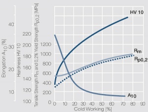
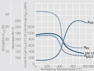
Technical grade pure nickel commonly contains 99.0 to 99.8 wt% Ni and up to 1 wt% Co. Other ingredients are iron and manganese Table 7 and Table 8. Work hardening and softening behavior of nickel are shown in (Figs. 5 – 6).
One of the significant properties of nickel is its modulus of elasticity which is almost twice as high as that of copper. At temperatures up to 345°C nickel is ferro-magnetic. Nickel has a high corrosion resistance, is very ductile, and easy to weld and clad. It is of great importance as a backing material for multiple layer weld profiles. In addition nickel is used as an intermediate layers for thin claddings, acting as an effective diffusion barrier between copper containing carrier materials and goldand palladium-based contact materials.
Because of the always present thin oxide layer on its surface, nickel is not suitable as a contact material for switching contacts.
Figure 5 Strain hardening of technical pure nickel by cold working
Figure 6 Softening of technical grad nickel after annealing for 3 hrs after 50% cold working
Nickel Alloys
Because of its low electrical conductivity NiCu30Fe is besides pure Ni and CuNi alloys the most widely used backing material for weldable contact components. With 1 – 2 wt% additives of Fe as well as 0.5 – 1 wt% Mn and Co the mechanical strength of the binary alloy NiCu30 can be increased.
The strength values of NiCu30Fe are significantly higher than those of the copper rich CuNi alloys (Figs. 7 – 8). The good spring properties and thermal stability of NiCu30Fe make it a suitable material for the use as thermally stressed contact springs.
Figure 7 Strain hardening of NiCu30Fe by cold working
Figure 8 Softening of NiCu30Fe after annealing for 0.5 hrs and after 80% cold working
| Material Designation WST-Nr. EN UNS |
Composition [wt%] |
Density [g/cm3] |
Electrical Conductivity |
Electrical Resistivity [μΩ·cm] |
Thermal Conductivity [W/(m·K)] |
Coeff. of Linear Thermal Expansion [10-6/K] |
Modulus of Elasticity [GPa] |
Softening Temperature (approx. 10% loss in strength) [°C] |
Melting Temp Range [°C] | |
|---|---|---|---|---|---|---|---|---|---|---|
| [MS/m] | [% IACS] | |||||||||
| Ni 99,2 2.4066 17740 N02200 |
Mn < 0.35 Cu < 0.25 Si < 0.25 Fe < 0.4 C < 0.01 Ni > 99.2 |
8.9 | 11 | 19 | 9.0 | 70,5 | 13.0 | 207 | ca. 450 | 1140 |
| NiCu30Fe 2.4360 17743 N04400 |
Cu 28 - 34 Fe 1 - 2.5 Ni Rest Be 1.85 - 2.05 |
8.8 | 2.1 | 3.6 | 48.0 | 22 | 14.0 | 185 | ca. 420 | 1300 - 1350 |
| NiBe2 N03360 |
Ti 0.4 - 0.6 Ni Rest |
8.3 | 5.0a | 8.6 | 0.2a | 48 | 14.4 | 210 | 1380 | |
asolution annealed, and hardened
| Material | Hardness Condition |
Tensile Strength Rm [MPa] |
0,2% Yield Strength Rp02 [MPa] |
Elongation A50 [%] |
Vickers Hardness HV |
Spring Bending Limit σFB [MPa] |
Fatigue Strength σBW [MPa] |
|---|---|---|---|---|---|---|---|
| Ni99,2 | R 380 | ≥ 380 | ≥ 100 | ≥ 40 | ≥ 100 | ||
| NiCu30Fe | R 400 R 700 |
400 - 600 700 - 850 |
≥ 160 ≥ 600 |
≥ 30 ≥ 4 |
95 - 125 200 - 240 |
||
| NiBe2 | R 700a R 1300a R 1500b R 1900b R 1800c |
≥ 700 ≥ 1300 ≥ 1500 ≥ 1900 ≥ 1800 |
≥ 300 ≥ 1200 ≥ 1100 ≥ 1750 ≥ 1700 |
≥ 30 ≥ 1 ≥ 12 ≥ 1 ≥ 5 |
≥ 170 ≥ 370 ≥ 450 ≥ 520 ≥ 500 |
≥ 1400 |
≥ 400 |
asolution annealed, and cold rolled
bsolution annealed, cold rolled, and precipitation hardened
csolution annealed, cold rolled, and precipitation hardened at mill (mill hardened)
Nickel-Beryllium Alloys
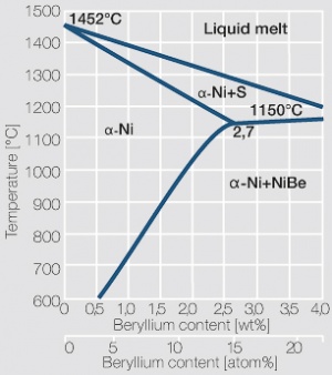
Because of decreasing solubility of beryllium in nickel with decreasing temperature NiBe can be precipitation hardened similar to CuBe Figure 9. The maximum soluble amount of Be in Ni is 2.7 wt% at the eutectic temperature of 1150°C. to achieve a high hardness by precipitation hardening NiBe, similar to CuBe, is annealed at 970 - 1030°C and rapidly quenched to room temperature. Soft annealed material is easily cold formed and after stamping and forming an hardening anneal is performed at 480 to 500°C for 1 to 2 hours.
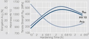
Commercial nickel-beryllium alloys contain 2 wt% Be. Compared to CuBe2 the NiBe2 materials have a significantly higher modulus of elasticity but a much lower electrical conductivity. The mechanical strength is higher than that of CuBe2 Figure 10, the spring bending force limit can exceed values of over 1400 MPa and the fatigue strength reaches approximately 400 MPa.
A further advantage of NiBe2 is its high temperature stability. Cold worked and subsequently precipitation hardened NiBe2 can withstand sustained temperatures of 400 - 650°C, depending on ist pre-treatment.
Similar to CuBe materials, NiBe alloys are available in mill hardened in various conditions or also already precipitation hardened at the manufacturer.
Nickel-beryllium alloys are recommended for mechanically and thermally highly stressed spring components. For some applications their ferro-magnetic properties can also be advantageous.
Triple-Layer Carrier Materials
Manufacturing of triple-layer carrier materials is usually performed by cold rollcladding. The three materials cover each other completely. The advantage of this composite material group is that the different mechanical and physical properties of the individual components can be combined with each other.
Depending on the intended application the following layer systems are utilized:
- Conduflex N
CuSn6 - Cu - CuSn6
The high electrical and thermal conductivity as well as the current carrying capacity of copper is combined with the spring properties of the tin bronze. Conduflex N strips are used in a thickness range of 0.1 – 1,5 mm in a maximum width of 140 mm.
- Cu - FeNi36 (Invar) - Cu
The high electrical conductivity and ductility of copperis combined with the low coefficient of thermal conductivity of the Invar alloy. The dimensionsional range is 0.2 – 1.8 mm in thickness with a maximum width of 140 mm.
- Cu – Fe or Steel – Cu
The high electrical conductivity and good arc mobility properties of copper are combined with the mechanical strength and magnetic properties of iron or steel. The thickness and width range of material strips are the same of the ones for Cu – Invar – Cu system.
The thickness ratios of the components can be selected according to the application requirements. The two outer layers usually have the same thickness.
Thermostatic Bimetals
Thermostatic bimetals are composite materials consisting of two or three layers of materials with different coefficients of thermal expansion. They are usually bonded together by cladding. If such a material part is heated either directly through current flow or indirectly through heat conduction or radiation, the different expansion between the active (strong expansion) and passive (low expansion) layer causes bending of the component part.
Directional or force effects on the free end of the thermostatic bimetal part is then used as a trigger or control mechanism in thermostats, protective switches, or in control circuits. Depending on the required function of the thermostatic bimetal component different design shapes are used:
- Straight or U-shaped strips for nearly linear motion
- Circular discs for small linear motions with high force
- Spirals and filament spring shapes for circular motion
- Stamped and formed parts for special designs and applications
The wide variety of thermostatic bimetal types is specified mostly through DIN 1715 and/or applicable ASTM standards Table 9. The different types have varying material compositions for the active and passive side of the materials. The mostly used alloys are iron-nickel and manganese-copper-nickel. Mainly used in circuit protection switches (i.e. circuit breakers) some thermo-bimetals include an intermediate layer of copper or nickel which allows to design parts with a closely controlled electrical resistance.
| Designation DIN 1715 |
Designation ASTM |
Specific Thermal Deflection [106/K] |
Sprecific Electrical Resistance k [μΩ·m] |
Typical Application Range [°C] |
Application Limit [°C] |
Composition |
|---|---|---|---|---|---|---|
| TB 20110 TB 1577A TB1170A |
TM 2 TM 8 TM 1 TM 3 TM 4 |
21.1 15.3 15.5 14.2 11.7 10.6 8.5 |
1.12 1.41 0.79 0.78 0.70 0.71 0.66 |
- 70 – + 260 - 70 – + 260 - 70 – + 370 - 70 – + 370 - 70 – + 425 - 70 – + 480 - 70 – + 425 |
350 350 450 450 480 540 540 |
Two components |
| TB 1517 TB 1511 TB 1303 TB 1109 |
TM 28 TM 26 TM 25 TM 24 |
14.9 14.9 14.3 13.9 13.2 13.1 12.3 11.5 |
0.17 0.11 0.15 0.08 0.03 0.05 0.03 0.09 |
- 70 – + 260 - 70 – + 260 - 70 – + 315 - 70 – + 315 - 70 – + 260 - 70 – + 315 - 70 – + 315 - 70 – + 380 |
400 400 350 350 300 350 350 400 |
Three components with Cu intermediale layer |
| TB 1555 TB 1435 TB 1425 |
TM 17 TM 15 TM 13 TM 11 TM 9 |
15.0 14.8 14.2 14.1 14.0 13.6 12.8 10.7 |
0.55 0.40 0.66 0.50 0.25 0.33 0.25 0.17 |
- 70 – + 260 - 70 – + 260 - 70 – + 370 - 70 – + 370 - 70 – + 260 - 70 – + 370 - 70 – + 370 - 70 – + 370 |
450 450 480 480 450 480 480 480 |
Three components with Ni intermediale layer |
Design Formulas
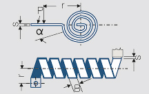
For the design and calculation of the most important thermostatic-bimetal parts formulas are given in Table 10. The necessary properties can be extracted for the most common materials from Table 9. The values given are valid only for a temperature range up to approximately 150°C. For higher temperatures data can be obtained from the materials manufacturer.
| Shape of the Thermostatic Bimetal | Deflection | Mechanical Action Force | Thermal Action Force | |
| Cantilevered strip | ||||
| Dual supported strip | ||||
| U-shaped element | ||||
| Spiral | ||||
| Helical spring | ||||
| Disc | ||||
| Reversed strip | ||||
| Reversed U-shaped element | ||||
| Deflection in mm | Width in mm | |||
| Turn angle in ° | Diameter in mm | |||
| Force in N | Radius in mm | |||
| Temperature difference in K | Specific therm. Deflection in 1/K | |||
| Thickness in mm | Thermal action force constant |
|||
| Free moving length in mm | Mechan. action force constant in |
Stress Force Limitations
For all calculations according to the formulas in Table 10 one should check if the thermally or mechanically induced stress forces stay below the allowed bending force limit. The following formulas are applicable for calculating the allowable load (Force Pmax or momentum Mmax):
| Single side fixed strip | |
| Both sides fixed strip | |
| Spiral or filament | |
| Disc |
= bending stress
Kommentare
- ↑ Als Einheiten für die Kennzeichnung der elektrischen Leitfähigkeit sind MS/m and m/Ω.mm2 gebräuchlich. Häufig erfolgt auch die Angabe in % IACS ( International Annealed Copper Standard), wobei 100% IACS der Leitfähigkeit von Kupfer mit 58 MS/m entspricht.
Für die Bezeichnung von Festigkeitszuständen gelten die Einheiten N/mm2 und MPa.
1 MS/m entspricht 1 m/Ωmm2
1 MPa entspricht 1 N/mm2
Referenzen
ASM Handbuch Volume 2, 10th Edition: Properties and Selection of Nonferrous
Alloys and Special Purpose Materials, ASM International, Cleveland OH, USA 1990
Wieland-Kupferwerkstoffe. Wieland-Werke AG, Ulm 1999
Rau, G.: Metallische Verbundwerkstoffe. Werkstofftechnische
Verlagsgesellschaft, Karlsruhe 1977
Kayser, O., Pawlek, F., Reichel, K.: Die Beeinflussung der Leitfähigkeit reinsten
Kupfers durch Beimengungen. Metall 8 (1954) 532-537
Dies, K.: Kupfer und Kupferlegierungen in der Technik. Springer-Verlag, Berlin, Heidelberg, New York, 1967
Gerlach,U.; Kreye, H.: Gefüge und mechanische Eigenschaften der Legierung
CuNi9Sn2. Metall 32 (1978) 1112-1115
Beryvac, Firmenschrift Vakuumschmelze GmbH, Hanau 1974
Beryvac 520, Firmenschrift Vacuumschmelze GmbH, Hanau 1975
Kupfer-Beryllium, Firmenschrift Brush Wellman
Kreye, H.; Nöcker, H.; Terlinde, G.: Schrumpfung und Verzug beim Aushärten von Kupfer-Beryllium-Legierungen. Metall 29 (1975) 1118-1121
