Difference between revisions of "Faustregeln für die Kontaktdimensionierung"
From Electrical Contacts
Doduco Admin (talk | contribs) (→Faustregeln für die Kontaktdimensionierung) |
Doduco Admin (talk | contribs) (→Faustregeln für die Kontaktdimensionierung) |
||
| Line 48: | Line 48: | ||
*'''Faustregeln zur Dimensionierung von Kontaktnieten''' | *'''Faustregeln zur Dimensionierung von Kontaktnieten''' | ||
<figure id="fig:Failure probability of a contact as a function of the voitage"> | <figure id="fig:Failure probability of a contact as a function of the voitage"> | ||
| − | [[File:General Rules for Dimensioning of Contact Rivets.jpg|left|Figure 1: Faustregeln zur Dimensionierung von Kontaktnieten]] | + | [[File:General Rules for Dimensioning of Contact Rivets.jpg|left|thumb|Figure 1: Faustregeln zur Dimensionierung von Kontaktnieten]] |
</figure> | </figure> | ||
{| class="twocolortable" style="text-align: left; font-size: 12px;width:100%" | {| class="twocolortable" style="text-align: left; font-size: 12px;width:100%" | ||
| Line 163: | Line 163: | ||
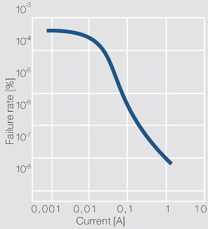
<figure id="fig:Failure probability of a contact as a function of the current"> | <figure id="fig:Failure probability of a contact as a function of the current"> | ||
| − | [[File:Failure probability of a contact as a function of the current.jpg|left|Figure 3: Ausfallwahrscheinlichkeit eines Kontaktes in Abhängigkeit von der Stromstärke (nach Kirchdorfer); Ag/Ni10; 10 mA; Ag/Ni10; F<sub>k</sub> = 0.45 N; U = 24 V]] | + | [[File:Failure probability of a contact as a function of the current.jpg|left|thumb|Figure 3: Ausfallwahrscheinlichkeit eines Kontaktes in Abhängigkeit von der Stromstärke (nach Kirchdorfer); Ag/Ni10; 10 mA; Ag/Ni10; F<sub>k</sub> = 0.45 N; U = 24 V]] |
</figure> | </figure> | ||
</div> | </div> | ||
Revision as of 07:45, 4 January 2023
Faustregeln für die Kontaktdimensionierung
- Empfohlene Mindestkontaktkräfte bei leicht reibender Kontaktgabe:
| Gold | 0.03 N |
| Silber | 0.1 N |
| Wolfram | 0.5 N |
- Richtwerte für Kontaktkräfte:
| Signalrelais | ≥ 3 cN |
| Netzrelais | ≥ 20 cN |
| Kfz-Relais | ≥ 20 cN |
| Motorschalter (Schütze) (Silber-Metalloxid-Kontakte) |
0.05 - 0.08 N/A |
| Leistungsschalter | 0.1 - 0.2 N/A |
| Steckverbinder (Gold-Beschichtung) |
≥ 30 cN/Kontaktstelle |
| Steckverbinder (Silber-Beschichtung) |
≥ 50 cN/Kontaktstelle |
| Steckverbinder (Zinn-Beschichtung) |
≥ 1 N/Kontaktstelle |
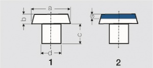
- Faustregeln zur Dimensionierung von Kontaktnieten
| Dimensionierung | Massivniet (1) | Bimetallniet (2) |
|---|---|---|
| a : d | 1.5 : 1 bis 2.5 : 1 | 2 : 1 bis 2.5 : 1 |
| a : b | 2.5 : 1 bis 10 : 1 | 3 : 1 bis 5 : 1 |
| c : b | ≥ 1 : 1 | ≥ 1 : 1 |
| b : s | ≥ 2 : 1 | |
| smin | ≈ 0.3 mm |
- Kopfdurchmesser bei elektrischer Belastung
| bei Wechselstrom: | ca. 1 – 1.5 A/mm² |
| für 1 A | min. 2 mm Kopfdurchmesser |
| 10 A | ca. 3 – 3.5 mm Kopfdurchmesser |
| 20 A | ca. 5 mm Kopfdurchmesser |
| bei Gleichstrom: | ca. 0.5 – 0.8 A/mm² |
- Kopfradius R bei elektrischer Belastung
| für I < 1 A | R ≈ 1,5 mm |
| I = 6 A | R ≈ 5 mm |
| I = 10 A | R ≈ 10 mm |
| I = 20 A | R ≈ 15 mm |
- Ausfallwahrscheinlichkeit von Einzel- und Doppelkontakten (nach Thielecke)
| Kontaktkraft[N] | Einzelkontakt | Doppelkontakt | ||
|---|---|---|---|---|
| Ag | AuNi 5, Pt | Ag | AuNi 5, Pt | |
| 0.04 | 1 x 10⁻⁴ | 2 x 10⁻⁸ | ||
| 0.1 | 2 x 10⁻³ | 4 x 10⁻⁵ | 8 x 10⁻⁵ | 8 x 10⁻⁹ |
| 0.2 | 1 x 10⁻⁴ | 8 x 10⁻⁶ | 4 x 10⁻⁶ | 4 x 10⁻⁸ |
| 0.3 | 5.5 x 10⁻⁶ | 1.5 x 10⁻⁶ | 1.8 x 10⁻⁷ | 3.2 x 10⁻¹⁰ |


