Difference between revisions of "Testing Procedures for Power Engineering"
(→13.4.2.2 Temperature Rise) |
(→13.4.2.4 Switching Capacity) |
||
| Line 240: | Line 240: | ||
====13.4.2.4 Switching Capacity==== | ====13.4.2.4 Switching Capacity==== | ||
| − | The main requirement for low voltage power switches is the withstanding of high short circuit currents. The short circuit switching capacity of power switches is determined in tests according to IEC/EN 60947-2 | + | The main requirement for low voltage power switches is the withstanding of high short circuit currents. The short circuit switching capacity of power switches is determined in tests according to IEC/EN 60947-2 (Tab. 13.3). These test differentiate between the maximum short circuit current switching capacity (ultimate current limit) I<sub>CU</sub> and the operational (or service) short circuit current capacity I<sub>CS</sub> . |
When specifying I<sub>CU</sub> it must be guaranteed that short circuit current up to the maximum limit value can be interrupted safely. After its occurrence it must be possible to switch on one additional time onto the not yet eliminated short circuit and again interrupt this short circuit current again safely. The switch does not have to be functional any more after this second interruption. A switch specified for I<sub>CS</sub> must still be capable to protect the circuit and be further usable within certain limitations. | When specifying I<sub>CU</sub> it must be guaranteed that short circuit current up to the maximum limit value can be interrupted safely. After its occurrence it must be possible to switch on one additional time onto the not yet eliminated short circuit and again interrupt this short circuit current again safely. The switch does not have to be functional any more after this second interruption. A switch specified for I<sub>CS</sub> must still be capable to protect the circuit and be further usable within certain limitations. | ||
| Line 248: | Line 248: | ||
Table 13.3: Testing for the Short Circuit Breaking Capacity of Low Voltage | Table 13.3: Testing for the Short Circuit Breaking Capacity of Low Voltage | ||
Power Switches According to IEC/EN 60947-2 (Shortened Summary) | Power Switches According to IEC/EN 60947-2 (Shortened Summary) | ||
| − | |||
===13.4.3 Testing According to UL and CSA=== | ===13.4.3 Testing According to UL and CSA=== | ||
Revision as of 13:54, 23 April 2014
13.4 Testing Procedures for Power Engineering
The testing of electrical contacts for power engineering applications serves on the one hand the continuous quality assurance, on the other one the new and improvement development efforts for contact materials. To optimize the contact and switching performance contact materials and device designs have to complement each other. The success of such optimizing is proven through switching tests.
The assessment of contact materials is performed using metallurgical test methods as well as switching tests in model test set-ups and in commercial switching devices. While physical properties such as melting and boiling point, electrical conductivity, etc. are fundamental for the selection of the base metals and the additional components of the materials, they cannot provide a clear indication of the contact and switching behavior. Metallurgical evaluations and tests are used primarily for determining material and working defects. The actual contact and switching behavior can however only be determined through switching tests in a model switch or preferably in the final electromechanical device.
Model testing devices offer the possibility of quick ratings of the make and break behavior and give a preliminary classification of potential contact materials. Since such tests are performed under ideal conditions they cannot replace switching tests in actual devices.
The electrical testing of commercially produced switching devices should follow DIN EN or IEC standards and rules. Special test standards exist for each type of switching device which are differentiated by:
- Make capacity
- Break capacity
- Electrical life
- Temperature rise
The following chapters are limited to metallurgical analysis and the testing of the most important properties of switching devices such as electrical life, temperature rise, and switching capacity.
13.4.1 Metallurgical Analysis
The main characteristic for the appraisal of contact materials for power engineering is the optical evaluation of their microstructure in a metallographic mount. This provides a picture of the internal structure of the materials. It allows detecting structural in-homogeneity, grain boundary enrichments, cracks, material separations, or defects in the brazing interface. The metallographic view is however limited to the one two-dimensional plain in which the mounting cut was made.
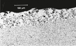
Figure 1 (Fig. 13.11) shows the microstructure of a Ag/CdO contact material after being affected by electrical arcing. In the lower part the starting material structure is visible. In the upper part the de-mixing of the composite material through the effects of the switching arc is clearly demonstrated. This “switching structure” shows in certain areas depletion of metal oxide which increases the probability of contact welding during subsequenbt make operations. Additional analysis by X-ray probing in a scanning electron microscope (SEM) allows the micro analysis of the elements present in the contact surface region.
13.4.2 Testing According to IEC/EN
13.4.2.1 Electrical Life
The electrical life of contactors, motor switches, and auxiliary current switches used in power engineering is classified into use categories which are shown in Table 1 (Tab. 13.1).
The making and breaking currents for tests IEC/EN 60947-4-1 are shown in Table 2 (Tab. 13.2) for the different use categories.
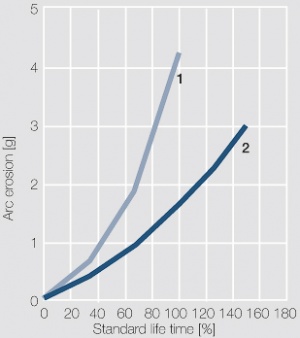
The electrical life of a motor switch is influenced primarily by arc erosion which is generated during make and break arcs on the contact surface. During AC-3 testing, for which the make current is six time the nominal rated current, the arc erosion is mainly caused by the make arcs, especially if frequent contact bounces > 2 ms occur. Therefore the bounce characteristic of switching devices primarily used for “normal” use in switching on and off electrical motors is of critical importance. If make and break currents are the same, as in the ultilisation categories AC-1 and AC-4, the break erosion dominates the arc erosion so much that make erosion can be neglected.
| Contactors, Motor Starters according to IEC/N60947-4-1 | |||||
|---|---|---|---|---|---|
| Type of current | Utilisation category | Typical application | |||
| Alternating current (AC) | AC-1 | Non-inductive or slightly inductive loads, resistance furnaces | |||
| AC-2 | Slip ring motors: starting, switch-off | ||||
| AC-3 | Squirrel-cage motors: starting, switch-off, switch-off during running4) | ||||
| AC-4 | Sqirrel-cage motors: starting, plugging, reversing, inching | ||||
| Direct current (DC) | DC-1 | Non-inductive or slightly inductive loads, resistance furnaces | |||
| DC-3 | Shunt motors: starting, plugging, reversing, inching, dynamic braking | ||||
| DC-5 | Series motors: starting, plugging, reversing, inching, dynamic braking | ||||
| Auxiliary Current Switches according to IEC/EN 160947-5-1 | |||||
| Type of current | Utilisation category | Typical application | |||
| Alternating current (AC) | AC-12 | Controlling resistive semiconductor loads in feed circuits of optoelectronics | |||
| AC-14 | Controlling small electromagnetic loads (72 VA max) | ||||
| AC-15 | Controlling electromagnetic loads (> 72 VA) | ||||
| Direct Current (DC) | DC-12 | Controlling resistive semiconductor loads in feed circuits of optoelectronics | |||
| DC-13 | Controlling of electro magnets under direct current | ||||
| DC-14 | Controlling of electromagnetic loads under direct current with power saving resistors in circuits | ||||
The electrical life for the utilization categories AC-3, DC-3, and DC-5 must be at a minimum 5% of the mechanical lifetime of a switching device. The conditions for make and break tests of auxiliary current switches and control circuit devices are described in IEC/EN 60947-5-1. Usually the electrical life of auxiliary switches is of lesser importance since these devices see only smaller loads. Under certain conditions however requirements for make and beak capacity can be as high as 10 times the nominal current. This results in very severe requirements on the dielectric strength and recovery voltage of the arc affected region immediately after arcing.
| Ultilisation Category | Current | Make operation | Break Operation | ||||
|---|---|---|---|---|---|---|---|
| Ie/A | I/Ie | U/Ue | cos φ | Ic/Ie | Ur/Ue | cos φ | |
| AC-1 | Alle Werte | 1 | 1 | 0.95 | 1 | 1 | 0.95 |
| AC-2 | Alle Werte | 2.5 | 1 | 0.65 | 2.5 | 1 | 0.65 |
| AC-3 | Ie ≤ 17 Ie > 17 |
6 6 |
1 1 |
0.65 0.35 |
1 1 |
0.17 0.17 |
0.65 0.35 |
| AC-4 | Ie ≤ 17 Ie > 17 |
6 6 |
1 1 |
0.65 0.35 |
6 6 |
1 1 |
0.65 0.35 |
| Ie/A | I/Ie | U/Ue | L/R [ms] | Ic/Ie | Ur/Ue | L/R [ms] | |
| DC-1 | All values | 1 | 1 | 1 | 1 | 1 | 1 |
| DC-3 | All values | 2.5 | 1 | 2 | 2.5 | 1 | 2 |
| DC-5 | All values | 2.5 | 1 | 7.5 | 2.5 | 1 | 7.5 |
Ie = Rated operational current
I = Make (ON) current
Ic = Break (OFF) current
Ue = Rated operational voltage
U = Voltage
Ur = Recovery voltage
13.4.2.2 Temperature Rise
Testing for temperature rise is required only for switching devices in the new stage. During use however over the entire life of the device no damages due to temperature rise are allowed in the device or at ist terminal points.

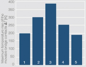
For the assessment of contact materials a temperature rise test is frequently performed after a specified number of switching operations accompanied by arcing Figure 2 (Fig. 13.13). The most important characteristic is the measured temeperature rise of the movable bridge contacts. If a certain upper limit of temperature is reached, adjacent plastic components may be irreversibly damaged.
13.4.2.3 Analysis of the Switching Sequence
In switching devices, which are actuated by AC actuator magnets, the contact parts can close and open synchronously at a specific phase angle relative to the voltage-zero of the supply voltage. Of similar importance is the sequence of closing and opening of the contacts with regards to the three phases. The closing and opening delays define at which time delay after the first phase (or pole) the other phases close and open.
Relevant experiments have shown that combined effects of synchronism, phase sequence and switching delay can, under severe adverse conditions, lead to extreme damage, especially on at least one of the phases or poles. They are the cause of early failure of this phase and therefore the complete switching device and can happen as early as after only 30% of the normally expected lifetime. Because of variations in the mechanical characteristics of switching devices from manufacturing processes life testing cannot be performed on one device alone. Only statistical analysis of tests from multiple device samples can be used as reliable results. Such a procedure is however time consuming and costly. If however every single switching operation during a test is monitored for bounce behavior, on- and off-switching synchronization and related phase sequencing and phase delays, the arc moving behavior, and especially arc energy which is transferred during make and break arcing to the contact pieces, and then these data are properly analyzed, is it possible to assess a specific contact material from a test in only one device alone. Only statistical analysis of tests from multiple device samples can be used as reliable results. Such a procedure is however time consuming and costly. If however every single switching operation during a test is monitored for bounce behavior, on- and offswitching synchronization and related phase sequencing and phase delays, the arc moving behavior, and especially arc energy which is transferred during make and break arcing to the contact pieces, and then these data are properly analyzed, is it possible to assess a specific contact material from a test in only one device.
13.4.2.4 Switching Capacity
The main requirement for low voltage power switches is the withstanding of high short circuit currents. The short circuit switching capacity of power switches is determined in tests according to IEC/EN 60947-2 (Tab. 13.3). These test differentiate between the maximum short circuit current switching capacity (ultimate current limit) ICU and the operational (or service) short circuit current capacity ICS .
When specifying ICU it must be guaranteed that short circuit current up to the maximum limit value can be interrupted safely. After its occurrence it must be possible to switch on one additional time onto the not yet eliminated short circuit and again interrupt this short circuit current again safely. The switch does not have to be functional any more after this second interruption. A switch specified for ICS must still be capable to protect the circuit and be further usable within certain limitations.
To safely withstand short circuit currents high requirements are imposed on the weld resistance of the materials used for the mating contacts. During short circuit switching the contact force between the contacts pairing is reduced by electromagnetic forces. Above a certain device specific current value the contacts will separate. This generates an electrical arc with contact material melting at its root points. During the next closing of the contacts this can cause contact welding, prohibiting the opening of the contacts during a subsequent short circuit and therefore eliminating the safety function of the switching device.
Table 13.3: Testing for the Short Circuit Breaking Capacity of Low Voltage Power Switches According to IEC/EN 60947-2 (Shortened Summary)
13.4.3 Testing According to UL and CSA
The test standards for North America according to UL (USA) and CSA (Canada) differ in part substantially from those of the IEC and harmonized European EN standards. In the US and Canada the standards differentiate between switchgear for power distribution, for example low voltage circuit breakers and power switches covered by UL 489 (UL = Underwriters Laboratories) and CSAC22.2 No. 5-02 (CSA = Canadian Standard Association) and those for industrial switching devices, for example contactors covered by UL 508 and CSA-C22.2 No. 14 respectively. For industrial controls contactors and other switching devices are often classified in the USA according to NEMA (National Electrical Manufacturers Association) current rating. North American standards emphasize the prevention of fires and therefore have high limit requirements on temperature rise. They also require larger air and creep gaps than those of IEC, which leads to significant differences in the design of the switches and their contact systems.


