Difference between revisions of "Tungsten and Molybdenum Based Materials"
Doduco Admin (talk | contribs) (→Copper–Tungsten Materials) |
Doduco Admin (talk | contribs) |
||
| (15 intermediate revisions by the same user not shown) | |||
| Line 8: | Line 8: | ||
<caption>'''<!--Table 2.35:-->Mechanical Properties of Tungsten and Molybdenum'''</caption> | <caption>'''<!--Table 2.35:-->Mechanical Properties of Tungsten and Molybdenum'''</caption> | ||
<table class="twocolortable"> | <table class="twocolortable"> | ||
| − | <tr><th><p class="s12">Material</p></th><th><p class="s12">Micro Structure Condition</p></th><th><p class="s12">Vickers</p><p class="s12">Hardness HV 10</p></th><th><p class="s12">Tensile Strength</p><p class="s12">[MPa]</p></th></tr><tr><td><p class="s12"> | + | <tr><th><p class="s12">Material</p></th><th><p class="s12">Micro Structure Condition</p></th><th><p class="s12">Vickers</p><p class="s12">Hardness HV 10</p></th><th><p class="s12">Tensile Strength</p><p class="s12">[MPa]</p></th></tr><tr><td><p class="s12">Tungsten</p></td><td><p class="s12">Lightly worked structure</p><p class="s12">(wire and strip > 1.0 mm thick)</p><p class="s12">Strongly worked structure</p><p class="s12">(wire and strip < 1.0 mm thick)</p><p class="s12">Re-crystallized structure</p></td><td><p class="s12">300 - 500</p><p class="s12">500 - 750</p><p class="s12">360</p></td><td><p class="s12">1000 - 1800</p><p class="s12">1500 - 5000</p><p class="s12">1000 - 1200</p></td></tr><tr><td><p class="s12">Molybdenum</p></td><td><p class="s12">Lightly worked structure</p><p class="s12">(wire and strip > 1.0 mm thick)</p><p class="s12">Strongly worked structure</p><p class="s12">(wire and strip < 1.0 mm thick)</p><p class="s12">Re-crystallized structure</p></td><td><p class="s12">140 - 320</p><p class="s12">260 - 550</p><p class="s12">140 - 160</p></td><td><p class="s12">600 - 1100</p><p class="s12">800 - 2500</p><p class="s12">600 - 900</p></td></tr></table> |
</figtable> | </figtable> | ||
=== Silver–Tungsten Materials=== | === Silver–Tungsten Materials=== | ||
| − | Ag/W contact materials combine the high electrical and thermal conductivity of silver with the high arc erosion resistance of the high melting tungsten metal (<xr id="tab:Physical Properties of | + | Ag/W contact materials combine the high electrical and thermal conductivity of silver with the high arc erosion resistance of the high melting tungsten metal (<xr id="tab:Physical Properties of Contact Materials Based on Silver-Tungsten, Silver-Tungsten Carbide and Silver Molybdenum"/><!--(Table 2.36)-->). The manufacturing of materials with typically 50-80 wt% tungsten is performed by the powder metallurgical processes of liquid phase sintering or by infiltration. Particle size and shape of the starting powders are determining the micro structure and the contact specific properties of this material group (<xr id="fig:Micro structure of Ag W 25 75"/><!--(Fig. 2.134)-->, <xr id="fig:Micro structure of Ag WC 50 50"/><!--(Fig. 2.135)--> and <xr id="tab:Physical Properties of Contact Materials Based on Silver-Tungsten, Silver-Tungsten Carbide and Silver Molybdenum"/>). |
| − | During repeated switching under arcing loads, tungsten oxides and mixed oxides (silver tungstates – Ag<sub>2</sub> WO<sub>4</sub>) are formed on the Ag/W surface, creating poorly conducting layers which increase the contact resistance and by this the temperature rise during current carrying. Because of this fact the Ag/W is paired in many applications with Ag/C contact parts. | + | During repeated switching under arcing loads, tungsten oxides and mixed oxides (silver tungstates – Ag<sub>2</sub> WO<sub>4</sub>) are formed on the Ag/W surface, creating poorly conducting layers which increase the contact resistance and by this the temperature rise during current carrying. Because of this fact the Ag/W is paired in many applications with Ag/C or Ag/WC/C contact parts. |
Silver–tungsten contact tips are used in a variety of shapes and are produced for the ease of attachment with a fine silver backing layer and quite often an additional thin layer of a brazing alloy. The attachment to contact carriers is usually done by brazing, but also by direct resistance welding for smaller tips. | Silver–tungsten contact tips are used in a variety of shapes and are produced for the ease of attachment with a fine silver backing layer and quite often an additional thin layer of a brazing alloy. The attachment to contact carriers is usually done by brazing, but also by direct resistance welding for smaller tips. | ||
| Line 29: | Line 29: | ||
!Silver<br/>Content<br/>[wt.%] | !Silver<br/>Content<br/>[wt.%] | ||
!Density<br/>[g/cm<sup>3</sup>] | !Density<br/>[g/cm<sup>3</sup>] | ||
| − | |||
| − | |||
| − | |||
!Electrical<br/>Conductivity<br/>[MS/m] | !Electrical<br/>Conductivity<br/>[MS/m] | ||
| − | !Vickers<br/>Hardness<br/>[ | + | !Vickers<br/>Hardness<br/>[HV5] |
|- | |- | ||
|Ag/W 50/50 [[#text-reference|<sup>1</sup>]]<br/> | |Ag/W 50/50 [[#text-reference|<sup>1</sup>]]<br/> | ||
| − | | | + | |47 - 53 |
| − | | | + | |12,9 - 13,9 |
| − | | | + | |29 - 38 |
| − | + | |110 - 175 | |
| − | |||
| − | |||
| − | | | ||
|- | |- | ||
|Ag/W 40/60 [[#text-reference|<sup>1</sup>]] | |Ag/W 40/60 [[#text-reference|<sup>1</sup>]] | ||
| − | | | + | |37 - 43 |
| − | | | + | |13,9 - 14,5 |
| − | | | + | |21 - 32 |
| − | + | |150 - 240 | |
| − | |||
| − | |||
| − | | | ||
|- | |- | ||
|Ag/W 35/65 [[#text-reference|<sup>1</sup>]] | |Ag/W 35/65 [[#text-reference|<sup>1</sup>]] | ||
| − | | | + | |32 - 38 |
| − | |14, | + | |14,1 - 15,1 |
| − | + | |21 - 31 | |
| − | + | |160 - 260 | |
| − | |||
| − | |||
| − | |||
| − | |||
| − | |||
| − | |||
| − | |||
| − | |||
| − | |||
| − | |||
| − | |||
| − | |||
| − | |||
| − | |||
| − | | | ||
| − | | | ||
| − | |||
| − | |||
| − | |||
| − | |||
| − | |||
|- | |- | ||
| − | |Ag/W | + | |Ag/W 32/68 [[#text-reference|<sup>1</sup>]] |
| − | | | + | |29 - 35 |
| − | | | + | |14,3 - 15,2 |
| − | | | + | |21 - 30 |
| − | + | |180 - 265 | |
| − | |||
| − | |||
| − | |180 - | ||
|- | |- | ||
|Ag/WC 60/40 [[#text-reference|<sup>1</sup>]] | |Ag/WC 60/40 [[#text-reference|<sup>1</sup>]] | ||
| − | | | + | |57 - 63 |
| − | |11,6 - | + | |11,6 - 12,2 |
| − | + | |21 - 29 | |
| − | + | |140 - 200 | |
| − | | | ||
| − | |||
| − | |||
| − | |||
| − | |||
| − | |||
| − | |||
| − | |||
| − | |||
| − | |||
| − | |||
| − | |140 - | ||
|- | |- | ||
|Ag/WC 40/60 [[#text-reference|<sup>1</sup>]] | |Ag/WC 40/60 [[#text-reference|<sup>1</sup>]] | ||
| − | | | + | |37 - 43 |
| − | |12, | + | |12,5 - 13,3 |
| − | | | + | |18 - 25 |
| − | + | |230 - 340 | |
| − | |||
| − | |||
| − | | | ||
|- | |- | ||
| − | |Ag/WC | + | |Ag/WC 80/16C2 [[#text-reference|<sup>2</sup>]] |
| − | |||
| − | |||
| − | |||
| − | |||
| − | |||
| − | |||
| − | |||
| − | |||
| − | |||
|80 - 84 | |80 - 84 | ||
| − | |9, | + | |9,2 - 9,9 |
| − | + | |30 - 38 | |
| − | + | |35 - 55 | |
| − | | | ||
| − | |35 | ||
| − | |||
|- | |- | ||
| − | |Ag/WC | + | |Ag/WC 80/17C3 [[#text-reference|<sup>2</sup>]] |
| − | | | + | |78 - 82 |
| − | |9, | + | |9,1 - 9,8 |
| − | + | |23 - 33 | |
| − | + | |35 - 55 | |
| − | | | ||
| − | | | ||
| − | |||
|- | |- | ||
| − | |Ag/ | + | |Ag/WC 80/19C1 [[#text-reference|<sup>2</sup>]] |
| − | | | + | |78 - 82 |
| − | |9, | + | |9,5 - 10,5 |
| − | + | |28 - 43 | |
| − | + | |40 - 60 | |
| − | | | ||
| − | |||
| − | | | ||
|- | |- | ||
| − | |Ag/ | + | |Ag/WC 70/28C2 [[#text-reference|<sup>2</sup>]] |
| − | | | + | |68 - 72 |
| − | |9, | + | |9,6 - 10,3 |
| − | | | + | |24 - 32 |
| − | + | |35 - 55 | |
| − | |||
| − | |||
| − | | | ||
|- | |- | ||
| − | |Ag/Mo | + | |Ag/Mo 65/35 [[#text-reference|<sup>1</sup>]] |
| − | | | + | |62 - 68 |
| − | | | + | |9,9 - 10,9 |
| − | | | + | |16 - 28 |
| − | + | |140 - 130 | |
| − | |||
| − | |||
| − | |140 - | ||
|- | |- | ||
|} | |} | ||
| Line 176: | Line 104: | ||
=== Silver–Tungsten Carbide Materials=== | === Silver–Tungsten Carbide Materials=== | ||
| − | This group of contact materials contains typically 40-65 wt-% of the very hard and erosion wear resistant tungsten carbide and the high conductivity silver (<xr id="fig:Micro structure of Ag WC 50 50"/><!--(Fig. 2.135)--> and <xr id="tab:Physical Properties of | + | This group of contact materials contains typically 40-65 wt-% of the very hard and erosion wear resistant tungsten carbide and the high conductivity silver (<xr id="fig:Micro structure of Ag WC 50 50"/><!--(Fig. 2.135)--> and <xr id="tab:Physical Properties of Contact Materials Based on Silver-Tungsten, Silver-Tungsten Carbide and Silver Molybdenum"/><!--(Table 2.36)-->). Compared to Ag/W the Ag/WC materials exhibit a higher resistance against contact welding (<xr id="tab:Contact and Switching Properties of Contact Materials Based on Silver – Tungsten (SIWODUR), Silver–Tungsten Carbide (SIWODUR C) and Silver Molybdenum (SILMODUR)"/><!--(Table 2.37)-->). The rise in contact resistance experienced with Ag/W is less pronounced in Ag/WC because during arcing, a protective gas layer of CO is formed, which limits the reaction of oxygen on the contact surface and therefore the formation of metal oxides. |
| − | Higher requirements on low temperature rise can be fulfilled by adding a small amount of graphite, which however increases the arc erosion. Silver–tungsten-carbide–graphite materials with for example | + | Higher requirements on low temperature rise can be fulfilled by adding a small amount of graphite, which however increases the arc erosion. Silver–tungsten-carbide–graphite materials with for example 19 wt% WC and 1 wt% graphite or 16 wt% WC and 2 wt% graphite are manufactured using the single tip press-sinter-repress (PSR) process (<xr id="fig:Micro structure of -Ag WC 27 C3"/><!--(Fig. 2.136)-->). |
The applications of Ag/WC contacts are similar to those for Ag/W (<xr id="tab:Contact and Switching Properties of Contact Materials Based on Silver – Tungsten (SIWODUR), Silver–Tungsten Carbide (SIWODUR C) and Silver Molybdenum (SILMODUR)"/><!--(Table 2.38)-->). | The applications of Ag/WC contacts are similar to those for Ag/W (<xr id="tab:Contact and Switching Properties of Contact Materials Based on Silver – Tungsten (SIWODUR), Silver–Tungsten Carbide (SIWODUR C) and Silver Molybdenum (SILMODUR)"/><!--(Table 2.38)-->). | ||
=== Silver–Molybdenum Materials=== | === Silver–Molybdenum Materials=== | ||
| − | Ag/Mo materials with typically 50-70 wt% molybdenum are usually produced by the powder metallurgical infiltration process (<xr id="fig:Micro structure of Ag Mo 35 65"/><!--(Fig. 2.137)--> and <xr id="tab:Physical Properties of | + | Ag/Mo materials with typically 50-70 wt% molybdenum are usually produced by the powder metallurgical infiltration process (<xr id="fig:Micro structure of Ag Mo 35 65"/><!--(Fig. 2.137)--> and <xr id="tab:Physical Properties of Contact Materials Based on Silver-Tungsten, Silver-Tungsten Carbide and Silver Molybdenum"/><!--(Table 2.36)-->). Their contact properties are similar to those of Ag/W materials (<xr id="tab:Contact and Switching Properties of Contact Materials Based on Silver – Tungsten (SIWODUR), Silver–Tungsten Carbide (SIWODUR C) and Silver Molybdenum (SILMODUR)"/><!--(Table 2.37)-->). Since the molybdenum oxide is thermally less stable than tungsten oxide, the self-cleaning effect of Ag/Mo contact surface during arcing is more pronounced and the contact resistance remains lower than that of Ag/W. The arc erosion resistance of Ag/Mo however is lower than the one for Ag/W materials. The main applications for Ag/Mo contacts are in equipment protecting switching devices (<xr id="tab:Contact and Switching Properties of Contact Materials Based on Silver – Tungsten (SIWODUR), Silver–Tungsten Carbide (SIWODUR C) and Silver Molybdenum (SILMODUR)"/><!--(Table 2.38)-->). |
| Line 206: | Line 134: | ||
<caption>'''<!--Table 2.37:-->Contact and Switching Properties of Contact Materials Based on Silver – Tungsten, Silver–Tungsten Carbide and Silver Molybdenum'''</caption> | <caption>'''<!--Table 2.37:-->Contact and Switching Properties of Contact Materials Based on Silver – Tungsten, Silver–Tungsten Carbide and Silver Molybdenum'''</caption> | ||
<table class="twocolortable"> | <table class="twocolortable"> | ||
| − | <tr><th><p class="s12">Material</p></th><th><p class="s12">Properties</p></th></tr><tr><td><p class="s12">Silver-Tungsten</p><p class="s12"></p><p class="s12">Silver-tungsten carbide</p></td><td><p class="s12">Tendency to weld at high make currents in symmetrical pairing,</p><p class="s12">Higher contact resistance and higher temperature rise over increased number of operations through tungsten oxide and tungstate formation, especially for Ag/W,</p><p class="s12">High welding tendency of closed contacts during short circuit,</p><p class="s12">Very high arc erosion resistance, poor arc moving properties, High hardness and low formability,</p><p class="s12">Easy to braze and weld through Ag enriched backing layer</p></td></tr><tr><td><p class="s12">Silver-Tungsten Carbide plus | + | <tr><th><p class="s12">Material</p></th><th><p class="s12">Properties</p></th></tr><tr><td><p class="s12">Silver-Tungsten</p><p class="s12"></p><p class="s12">Silver-tungsten carbide</p></td><td><p class="s12">Tendency to weld at high make currents in symmetrical pairing,</p><p class="s12">Higher contact resistance and higher temperature rise over increased number of operations through tungsten oxide and tungstate formation, especially for Ag/W,</p><p class="s12">High welding tendency of closed contacts during short circuit,</p><p class="s12">Very high arc erosion resistance, poor arc moving properties, High hardness and low formability,</p><p class="s12">Easy to braze and weld through Ag enriched backing layer</p></td></tr><tr><td><p class="s12">Silver-Tungsten Carbide plus Graphite</p></td><td><p class="s12">Low contact resistance and low temperature rise through graphite addition,</p><p class="s12">Lower tendency to contact welding, Lower arc erosion resistance than Ag/WC</p></td></tr><tr><td><p class="s12">Silver-Molybdenum</p><p class="s12"></p></td><td><p class="s12">Better contact resistance stability due to less stable surface layers,</p><p class="s12">Lower arc erosion resistance than Ag/W</p></td></tr></table> |
</figtable> | </figtable> | ||
| Line 233: | Line 161: | ||
=== Copper–Tungsten Materials=== | === Copper–Tungsten Materials=== | ||
| − | Copper–tungsten materials with typically 50-85 wt% tungsten are produced by the infiltration process with the tungsten particle size selected according to the end application [[#figures4|(Figs. 5 – | + | Copper–tungsten materials with typically 50-85 wt% tungsten are produced by the infiltration process with the tungsten particle size selected according to the end application [[#figures4|(Figs. 5 – 6)]] <!--(Figs. 2.138 – 2.141)--> and (<xr id="tab:Physical properties of copper-tungsten materials"/><!--(Table 2.39)-->). To increase the wettability of the tungsten skeleton by copper a small amount of nickel < 1 wt% is added to the starting powder mix. |
<figtable id="tab:Physical properties of copper-tungsten materials"> | <figtable id="tab:Physical properties of copper-tungsten materials"> | ||
| Line 249: | Line 177: | ||
!Vickers<br/>Hardness<br/>[HV10] | !Vickers<br/>Hardness<br/>[HV10] | ||
|- | |- | ||
| − | |W/Cu 60/40 | + | |W/Cu 60/40 <br/> |
| − | | | + | |57 - 63 |
|12,9 - 13,3 | |12,9 - 13,3 | ||
|1083 | |1083 | ||
| Line 256: | Line 184: | ||
|38 - 45 | |38 - 45 | ||
|22 - 26 | |22 - 26 | ||
| − | | | + | |150 - 200 |
|- | |- | ||
| − | |W/Cu 65/35 | + | |W/Cu 65/35 |
|63 - 67 | |63 - 67 | ||
|13,6 - 14,0 | |13,6 - 14,0 | ||
| Line 267: | Line 195: | ||
|160 - 210 | |160 - 210 | ||
|- | |- | ||
| − | |W/Cu 70/30 | + | |W/Cu 70/30 |
| − | |||
| − | |||
| − | |||
| − | |||
| − | |||
| − | |||
| − | |||
| − | |||
| − | |||
| − | |||
| − | |||
| − | |||
| − | |||
| − | |||
| − | |||
| − | |||
| − | |||
| − | |||
| − | |||
| − | |||
| − | |||
| − | |||
| − | |||
| − | |||
| − | |||
| − | |||
| − | |||
| − | |||
| − | |||
| − | |||
| − | |||
| − | |||
| − | |||
| − | |||
| − | |||
| − | |||
|68 - 72 | |68 - 72 | ||
|13,9 - 14,4 | |13,9 - 14,4 | ||
| Line 310: | Line 202: | ||
|31 - 38 | |31 - 38 | ||
|18 - 22 | |18 - 22 | ||
| − | |160 - | + | |160 - 230 |
|- | |- | ||
| − | |W/Cu 75/25 | + | |W/Cu 75/25 |
|73 - 77 | |73 - 77 | ||
|14,6 - 15,2 | |14,6 - 15,2 | ||
| Line 321: | Line 213: | ||
|180 - 210 | |180 - 210 | ||
|- | |- | ||
| − | |W/Cu 80/20 | + | |W/Cu 80/20 |
|78 - 82 | |78 - 82 | ||
|15,3 - 15,9 | |15,3 - 15,9 | ||
| Line 328: | Line 220: | ||
|28 - 34 | |28 - 34 | ||
|16 - 20 | |16 - 20 | ||
| − | |180 - | + | |180 - 280 |
| − | |||
| − | |||
| − | |||
| − | |||
| − | |||
| − | |||
| − | |||
| − | |||
| − | |||
| − | |||
| − | |||
| − | |||
| − | |||
| − | |||
| − | |||
| − | |||
| − | |||
| − | |||
| − | |||
| − | |||
| − | |||
| − | |||
| − | |||
| − | |||
| − | |||
| − | |||
| − | |||
| − | |||
| − | |||
| − | |||
| − | |||
| − | |||
| − | |||
| − | |||
| − | |||
| − | |||
|- | |- | ||
|} | |} | ||
| − | |||
| − | |||
| − | |||
</figtable> | </figtable> | ||
| − | W/Cu materials exhibit a very high arc erosion resistance | + | W/Cu materials exhibit a very high arc erosion resistance. Compared to silver–tungsten materials, they are however less suitable to carry permanent current. |
With a solid tungsten skeleton, as it is the case for W/C infiltrated materials with 70-85 wt% tungsten, the lower melting component copper melts and vaporizes in the intense electrical arc. At the boiling point of copper (2567°C), the still solid tungsten is efficiently “cooled” and remains pretty much unchanged. | With a solid tungsten skeleton, as it is the case for W/C infiltrated materials with 70-85 wt% tungsten, the lower melting component copper melts and vaporizes in the intense electrical arc. At the boiling point of copper (2567°C), the still solid tungsten is efficiently “cooled” and remains pretty much unchanged. | ||
| Line 380: | Line 233: | ||
For high voltage load switches, the most advantageous contact system consists of a contact tulip and a contact rod. Both contact assemblies are usually made from the mechanically strong and high conductive CuCrZr material and W/Cu as the arcing tips. The thermally and mechanically highly stressed attachment between the two components is often achieved by utilizing electron beam welding or capacitor discharge percussion welding. Other attachment methods include brazing and cast-on of copper, followed by cold forming steps to increase hardness and strength. | For high voltage load switches, the most advantageous contact system consists of a contact tulip and a contact rod. Both contact assemblies are usually made from the mechanically strong and high conductive CuCrZr material and W/Cu as the arcing tips. The thermally and mechanically highly stressed attachment between the two components is often achieved by utilizing electron beam welding or capacitor discharge percussion welding. Other attachment methods include brazing and cast-on of copper, followed by cold forming steps to increase hardness and strength. | ||
| − | The main application areas for W/Cu materials are as arcing contacts in load and high power switching, in medium and high voltage switchgear as well as electrodes for spark gaps and over voltage arresters | + | The main application areas for W/Cu materials are as arcing contacts in load and high power switching, in medium and high voltage switchgear as well as electrodes for spark gaps and over voltage arresters. |
| − | |||
<div class="multiple-images"> | <div class="multiple-images"> | ||
<figure id="fig:Micro structure of W Cu 70 30 G"> | <figure id="fig:Micro structure of W Cu 70 30 G"> | ||
| − | [[File:Micro structure of W Cu 70 30 G.jpg|left|thumb|<caption>Micro structure of W/Cu 70/30 | + | [[File:Micro structure of W Cu 70 30 G.jpg|left|thumb|<caption>Micro structure of W/Cu 70/30 (coarse)</caption>]] |
| − | |||
| − | |||
| − | |||
| − | |||
</figure> | </figure> | ||
<figure id="fig:Micro structure of W Cu 70 30 F"> | <figure id="fig:Micro structure of W Cu 70 30 F"> | ||
| − | [[File:Micro structure of W Cu 70 30 F.jpg|left|thumb|<caption>Micro structure of W/Cu 70/30 | + | [[File:Micro structure of W Cu 70 30 F.jpg|left|thumb|<caption>Micro structure of W/Cu 70/30 (fine)</caption>]] |
</figure> | </figure> | ||
| − | |||
| − | |||
| − | |||
</div> | </div> | ||
<div class="clear"></div> | <div class="clear"></div> | ||
| − | |||
| − | |||
| − | |||
| − | |||
| − | |||
| − | |||
| − | |||
| − | |||
| − | |||
| − | |||
| − | |||
| − | |||
| − | |||
| − | |||
==References== | ==References== | ||
Latest revision as of 15:21, 27 March 2023
Contents
Tungsten and Molybdenum (Pure Metals)
Tungsten is characterized by its advantageous properties of high melting and boiling points, sufficient electrical and thermal conductivity and high hardness and density (Table 1). It is mainly used in the form of brazed contact tips for switching duties, that require a rapid switching sequence, such as horn contacts for cars and trucks.
Molybdenum has a much lesser importance as a contact material since it is less resistant against oxidation than tungsten. Both metals are however used in large amounts as components in composite materials with silver and copper.
Material | Micro Structure Condition | Vickers Hardness HV 10 | Tensile Strength [MPa] |
|---|---|---|---|
Tungsten | Lightly worked structure (wire and strip > 1.0 mm thick) Strongly worked structure (wire and strip < 1.0 mm thick) Re-crystallized structure | 300 - 500 500 - 750 360 | 1000 - 1800 1500 - 5000 1000 - 1200 |
Molybdenum | Lightly worked structure (wire and strip > 1.0 mm thick) Strongly worked structure (wire and strip < 1.0 mm thick) Re-crystallized structure | 140 - 320 260 - 550 140 - 160 | 600 - 1100 800 - 2500 600 - 900 |
Silver–Tungsten Materials
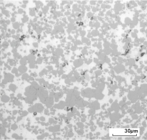
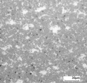
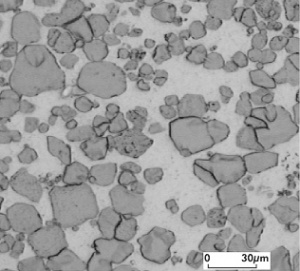
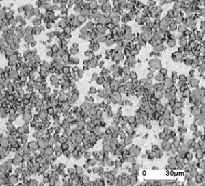
Ag/W contact materials combine the high electrical and thermal conductivity of silver with the high arc erosion resistance of the high melting tungsten metal (Table 2). The manufacturing of materials with typically 50-80 wt% tungsten is performed by the powder metallurgical processes of liquid phase sintering or by infiltration. Particle size and shape of the starting powders are determining the micro structure and the contact specific properties of this material group (Figure 1, Figure 2 and Table 2).
During repeated switching under arcing loads, tungsten oxides and mixed oxides (silver tungstates – Ag2 WO4) are formed on the Ag/W surface, creating poorly conducting layers which increase the contact resistance and by this the temperature rise during current carrying. Because of this fact the Ag/W is paired in many applications with Ag/C or Ag/WC/C contact parts.
Silver–tungsten contact tips are used in a variety of shapes and are produced for the ease of attachment with a fine silver backing layer and quite often an additional thin layer of a brazing alloy. The attachment to contact carriers is usually done by brazing, but also by direct resistance welding for smaller tips.
Ag/W materials are mostly used as the arcing contacts in disconnect switches for higher loads and as the main contacts in small and medium duty power switches and industrial circuit breakers (Table 4). In north and south america they are also used in large volumes in miniature circuit breakers of small to medium current ratings in domestic wiring as well as for commercial power distribution.
| Material | Silver Content [wt.%] |
Density [g/cm3] |
Electrical Conductivity [MS/m] |
Vickers Hardness [HV5] |
|---|---|---|---|---|
| Ag/W 50/50 1 |
47 - 53 | 12,9 - 13,9 | 29 - 38 | 110 - 175 |
| Ag/W 40/60 1 | 37 - 43 | 13,9 - 14,5 | 21 - 32 | 150 - 240 |
| Ag/W 35/65 1 | 32 - 38 | 14,1 - 15,1 | 21 - 31 | 160 - 260 |
| Ag/W 32/68 1 | 29 - 35 | 14,3 - 15,2 | 21 - 30 | 180 - 265 |
| Ag/WC 60/40 1 | 57 - 63 | 11,6 - 12,2 | 21 - 29 | 140 - 200 |
| Ag/WC 40/60 1 | 37 - 43 | 12,5 - 13,3 | 18 - 25 | 230 - 340 |
| Ag/WC 80/16C2 2 | 80 - 84 | 9,2 - 9,9 | 30 - 38 | 35 - 55 |
| Ag/WC 80/17C3 2 | 78 - 82 | 9,1 - 9,8 | 23 - 33 | 35 - 55 |
| Ag/WC 80/19C1 2 | 78 - 82 | 9,5 - 10,5 | 28 - 43 | 40 - 60 |
| Ag/WC 70/28C2 2 | 68 - 72 | 9,6 - 10,3 | 24 - 32 | 35 - 55 |
| Ag/Mo 65/35 1 | 62 - 68 | 9,9 - 10,9 | 16 - 28 | 140 - 130 |
Silver–Tungsten Carbide Materials
This group of contact materials contains typically 40-65 wt-% of the very hard and erosion wear resistant tungsten carbide and the high conductivity silver (Figure 2 and Table 2). Compared to Ag/W the Ag/WC materials exhibit a higher resistance against contact welding (Table 4). The rise in contact resistance experienced with Ag/W is less pronounced in Ag/WC because during arcing, a protective gas layer of CO is formed, which limits the reaction of oxygen on the contact surface and therefore the formation of metal oxides.
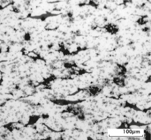
Higher requirements on low temperature rise can be fulfilled by adding a small amount of graphite, which however increases the arc erosion. Silver–tungsten-carbide–graphite materials with for example 19 wt% WC and 1 wt% graphite or 16 wt% WC and 2 wt% graphite are manufactured using the single tip press-sinter-repress (PSR) process (Figure 3).
The applications of Ag/WC contacts are similar to those for Ag/W (Table 4).
Silver–Molybdenum Materials
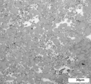
Ag/Mo materials with typically 50-70 wt% molybdenum are usually produced by the powder metallurgical infiltration process (Figure 4 and Table 2). Their contact properties are similar to those of Ag/W materials (Table 4). Since the molybdenum oxide is thermally less stable than tungsten oxide, the self-cleaning effect of Ag/Mo contact surface during arcing is more pronounced and the contact resistance remains lower than that of Ag/W. The arc erosion resistance of Ag/Mo however is lower than the one for Ag/W materials. The main applications for Ag/Mo contacts are in equipment protecting switching devices (Table 4).
Material | Properties |
|---|---|
Silver-Tungsten Silver-tungsten carbide | Tendency to weld at high make currents in symmetrical pairing, Higher contact resistance and higher temperature rise over increased number of operations through tungsten oxide and tungstate formation, especially for Ag/W, High welding tendency of closed contacts during short circuit, Very high arc erosion resistance, poor arc moving properties, High hardness and low formability, Easy to braze and weld through Ag enriched backing layer |
Silver-Tungsten Carbide plus Graphite | Low contact resistance and low temperature rise through graphite addition, Lower tendency to contact welding, Lower arc erosion resistance than Ag/WC |
Silver-Molybdenum | Better contact resistance stability due to less stable surface layers, Lower arc erosion resistance than Ag/W |
| Material | Application Examples | Form of Supply |
|---|---|---|
| Ag/W |
Circuit breakers (not current limiting) | Contact tips, brazed and welded contact parts |
| Ag/W Ag/WC Ag/WC/C |
(Main) Power switches paired with Ag/C) Fault current circuit breakers | |
| Ag/Mo |
Device protection switches |
Copper–Tungsten Materials
Copper–tungsten materials with typically 50-85 wt% tungsten are produced by the infiltration process with the tungsten particle size selected according to the end application (Figs. 5 – 6) and (Table 5). To increase the wettability of the tungsten skeleton by copper a small amount of nickel < 1 wt% is added to the starting powder mix.
| Material | Tungsten Content [wt.%] |
Density [g/cm3] |
Melting Point [°C] |
Electrical Resistivity [µΩ*cm] |
Electrical Conductivity [% IACS] |
Electrical Conductivity [MS/m] |
Vickers Hardness [HV10] |
|---|---|---|---|---|---|---|---|
| W/Cu 60/40 |
57 - 63 | 12,9 - 13,3 | 1083 | 3,85 - 4,55 | 38 - 45 | 22 - 26 | 150 - 200 |
| W/Cu 65/35 | 63 - 67 | 13,6 - 14,0 | 1083 | 4,17 - 5,0 | 34 - 41 | 20 - 24 | 160 - 210 |
| W/Cu 70/30 | 68 - 72 | 13,9 - 14,4 | 1083 | 3,85 - 5,56 | 31 - 38 | 18 - 22 | 160 - 230 |
| W/Cu 75/25 | 73 - 77 | 14,6 - 15,2 | 1083 | 4,76 - 5,88 | 29 - 36 | 17 - 21 | 180 - 210 |
| W/Cu 80/20 | 78 - 82 | 15,3 - 15,9 | 1083 | 5,0 - 6,25 | 28 - 34 | 16 - 20 | 180 - 280 |
W/Cu materials exhibit a very high arc erosion resistance. Compared to silver–tungsten materials, they are however less suitable to carry permanent current.
With a solid tungsten skeleton, as it is the case for W/C infiltrated materials with 70-85 wt% tungsten, the lower melting component copper melts and vaporizes in the intense electrical arc. At the boiling point of copper (2567°C), the still solid tungsten is efficiently “cooled” and remains pretty much unchanged.
During very high thermal stress on the W/Cu contacts, for example during short circuit currents > 40 kA, the tungsten skeleton requires special high mechanical strength. For such applications, a high temperature sintering of tungsten from selected particle size powder is applied before the usual infiltration with copper.
For high voltage load switches, the most advantageous contact system consists of a contact tulip and a contact rod. Both contact assemblies are usually made from the mechanically strong and high conductive CuCrZr material and W/Cu as the arcing tips. The thermally and mechanically highly stressed attachment between the two components is often achieved by utilizing electron beam welding or capacitor discharge percussion welding. Other attachment methods include brazing and cast-on of copper, followed by cold forming steps to increase hardness and strength.
The main application areas for W/Cu materials are as arcing contacts in load and high power switching, in medium and high voltage switchgear as well as electrodes for spark gaps and over voltage arresters.
