Difference between revisions of "Faustregeln für die Kontaktdimensionierung"
From Electrical Contacts
Doduco Admin (talk | contribs) |
Teitscheid (talk | contribs) (temp edit) |
||
| (7 intermediate revisions by 2 users not shown) | |||
| Line 46: | Line 46: | ||
| − | + | *'''General Rules for Dimensioning of Contact Rivets''' | |
| − | [[File:General Rules for Dimensioning of Contact Rivets.jpg|left| | + | |
| − | + | [[File:General Rules for Dimensioning of Contact Rivets.jpg|left|General Rules for Dimensioning of Contact Rivets]] | |
{| class="twocolortable" style="text-align: left; font-size: 12px;width:100%" | {| class="twocolortable" style="text-align: left; font-size: 12px;width:100%" | ||
|- | |- | ||
| − | ! | + | !Dimensioning |
| − | ! | + | !Solid Rivets (1) |
| − | ! | + | !Composite Rivets (2) |
|- | |- | ||
|a : d | |a : d | ||
| Line 77: | Line 77: | ||
| − | *''' | + | *'''Head diameter for electrical loads''' |
| + | |||
| + | {| class="twocolortable" style="text-align: left; font-size: 12px;width:40%" | ||
| + | |- | ||
| + | |For AC currents: | ||
| + | |approx. 1 – 1.5 A/mm² | ||
| + | |- | ||
| + | |For 1 A | ||
| + | |min. 2 mm head diameter | ||
| + | |- | ||
| + | |10 A | ||
| + | |approx. 3 – 3.5 mm head diameter | ||
| + | |- | ||
| + | |20 A | ||
| + | |approx. 5 mm head diameter | ||
| + | |- | ||
| + | |For DC currents: | ||
| + | |approx. 0.5 – 0.8 A/mm² | ||
| + | |} | ||
| + | |||
| + | |||
| + | *'''Head radius R for electrical loads''' | ||
| + | |||
| + | {| class="twocolortable" style="text-align: left; font-size: 12px;width:40%" | ||
| + | |- | ||
| + | |for I < 1 A | ||
| + | |R ≈ 1,5 mm | ||
| + | |- | ||
| + | |I = 6 A | ||
| + | |R ≈ 5 mm | ||
| + | |- | ||
| + | |I = 10 A | ||
| + | |R ≈ 10 mm | ||
| + | |- | ||
| + | |I = 20 A | ||
| + | |R ≈ 15 mm | ||
| + | |} | ||
| + | |||
| + | |||
| + | *'''Failure Probability of Single and Double (Bifurcated) Contacts''' (according to Thielecke) | ||
{| class="twocolortable" style="text-align: left; font-size: 12px;width:100%" | {| class="twocolortable" style="text-align: left; font-size: 12px;width:100%" | ||
|- | |- | ||
| − | ! | + | !Contact force[N] |
| − | !colspan=" | + | !colspan="4" style="text-align:center"|'''Single contact''' |
| − | |||
|- | |- | ||
! | ! | ||
| Line 119: | Line 157: | ||
<div class="multiple-images"> | <div class="multiple-images"> | ||
<figure id="fig:Failure probability of a contact as a function of the voitage"> | <figure id="fig:Failure probability of a contact as a function of the voitage"> | ||
| − | [[File:Failure probability of a contact as a function of the voitage.jpg|left| | + | [[File:Failure probability of a contact as a function of the voitage.jpg|left|Failure probability of a contact as a function of the voltage (according to Kirchdorfer); Ag/Ni10; 10 mA]] |
</figure> | </figure> | ||
<figure id="fig:Failure probability of a contact as a function of the current"> | <figure id="fig:Failure probability of a contact as a function of the current"> | ||
| − | [[File:Failure probability of a contact as a function of the current.jpg|left| | + | [[File:Failure probability of a contact as a function of the current.jpg|left|Failure probability of a contact as a function of the current (according to Kirchdorfer); Ag/Ni10; F<sub>k</sub> = 0.45 N; U = 24 V]] |
</figure> | </figure> | ||
</div> | </div> | ||
<div class="clear"></div> | <div class="clear"></div> | ||
| + | |||
| + | <xr id="fig:Failure probability of a contact as a function of the voitage"/><!--Fig. 6.18:--> Failure probability of a contact as a function of the voltage (according to Kirchdorfer); Ag/Ni10; 10 mA | ||
| + | |||
| + | <xr id="fig:Failure probability of a contact as a function of the current"/><!--Fig. 6.19:--> Failure probability of a contact as a function of the current (according to Kirchdorfer); Ag/Ni10; F = 0.45 N; U = 24 V | ||
==Referenzen== | ==Referenzen== | ||
Revision as of 20:50, 20 September 2014
Faustregeln für die Kontaktdimensionierung
- Empfohlene Mindestkontaktkräfte bei leicht reibender Kontaktgabe:
| Gold | 0.03 N |
| Silber | 0.1 N |
| Wolfram | 0.5 N |
- Richtwerte für Kontaktkräfte:
| Signalrelais | ≥ 3 cN |
| Netzrelais | ≥ 20 cN |
| Kfz-Relais | ≥ 20 cN |
| Motorschalter (Schütze) (Silber-Metalloxid-Kontakte) |
0.05 - 0.08 N/A |
| Leistungsschalter | 0.1 - 0.2 N/A |
| Steckverbinder (Gold-Beschichtung) |
≥ 30 cN/Kontaktstelle |
| Steckverbinder (Silber-Beschichtung) |
≥ 50 cN/Kontaktstelle |
| Steckverbinder (Zinn-Beschichtung) |
≥ 1 N/Kontaktstelle |
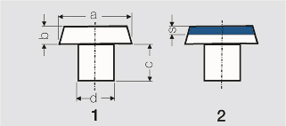
- General Rules for Dimensioning of Contact Rivets
| Dimensioning | Solid Rivets (1) | Composite Rivets (2) |
|---|---|---|
| a : d | 1.5 : 1 bis 2.5 : 1 | 2 : 1 bis 2.5 : 1 |
| a : b | 2.5 : 1 bis 10 : 1 | 3 : 1 bis 5 : 1 |
| c : b | ≥ 1 : 1 | ≥ 1 : 1 |
| b : s | ≥ 2 : 1 | |
| smin | ≈ 0.3 mm |
- Head diameter for electrical loads
| For AC currents: | approx. 1 – 1.5 A/mm² |
| For 1 A | min. 2 mm head diameter |
| 10 A | approx. 3 – 3.5 mm head diameter |
| 20 A | approx. 5 mm head diameter |
| For DC currents: | approx. 0.5 – 0.8 A/mm² |
- Head radius R for electrical loads
| for I < 1 A | R ≈ 1,5 mm |
| I = 6 A | R ≈ 5 mm |
| I = 10 A | R ≈ 10 mm |
| I = 20 A | R ≈ 15 mm |
- Failure Probability of Single and Double (Bifurcated) Contacts (according to Thielecke)
| Contact force[N] | Single contact | |||
|---|---|---|---|---|
| Ag | AuNi 5, Pt | Ag | AuNi 5, Pt | |
| 0.04 | 1 x 10⁻⁴ | 2 x 10⁻⁸ | ||
| 0.1 | 2 x 10⁻³ | 4 x 10⁻⁵ | 8 x 10⁻⁵ | 8 x 10⁻⁹ |
| 0.2 | 1 x 10⁻⁴ | 8 x 10⁻⁶ | 4 x 10⁻⁶ | 4 x 10⁻⁸ |
| 0.3 | 5.5 x 10⁻⁶ | 1.5 x 10⁻⁶ | 1.8 x 10⁻⁷ | 3.2 x 10⁻¹⁰ |
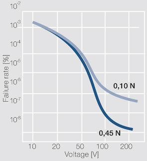
Figure 1 Failure probability of a contact as a function of the voltage (according to Kirchdorfer); Ag/Ni10; 10 mA
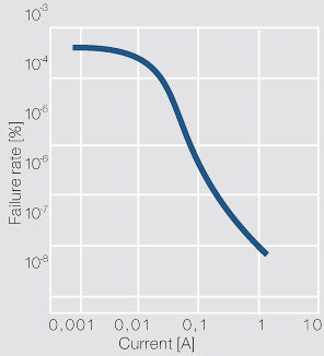
Figure 2 Failure probability of a contact as a function of the current (according to Kirchdorfer); Ag/Ni10; F = 0.45 N; U = 24 V


