Difference between revisions of "Contact Spring Calculations"
Doduco Admin (talk | contribs) (Blanked the page) (Tag: Blanking) |
(→6.4.7 Contact Spring Calculations) |
||
| (19 intermediate revisions by 5 users not shown) | |||
| Line 1: | Line 1: | ||
| + | ===6.4.7 Contact Spring Calculations=== | ||
| + | [[File:One side fixed contact bending spring.jpg|right|thumb|One side fixed contact bending spring]] | ||
| + | Fig. 6.20: | ||
| + | One side fixed contact bending spring<br /> | ||
| + | L = Length of spring<br /> | ||
| + | E = Modulus of elasticity<br /> | ||
| + | B = Width of spring<br /> | ||
| + | F = Spring force<br /> | ||
| + | D = Thickness of spring<br /> | ||
| + | x = Deflection<br /> | ||
| + | max = maximum bending force | ||
| + | The influence of the dimensions can be illustrated best by using the single side fixed beam model (Fig. 6.20). For small deflections the following equation is valid: | ||
| + | :<math>F = \frac {3 x E x J}{L^3} x</math> | ||
| + | |||
| + | where J is the momentum of inertia of the rectangular cross section of the beam | ||
| + | :<math>J = \frac {B x D^3}{12}</math> | ||
| + | |||
| + | For springs with a circular cross-sectional area the momentum of inertia is | ||
| + | :<math>J=\pi D^4/64</math> | ||
| + | :<math>D= Durchmesser</math> | ||
| + | |||
| + | To avoid plastic deformation of the spring the max bending force σ<sub>max</sub> cannot be exceeded | ||
| + | :<math>\sigma _{max} = \frac {3 x E x D}{2L^2}x_{max}</math> | ||
| + | |||
| + | The stress limit is defined through the fatigue limit and the 0.2% elongation limit resp. | ||
| + | :<math>x _{max} = \frac {2 x L^2}{3 x D x E}R_{p0,2}</math> | ||
| + | |||
| + | <br />and/or<br /> | ||
| + | :<math>F _{max} = \frac {B x D^2}{6L}R_{p0,2}</math> | ||
| + | |||
| + | |||
| + | <li>'''Special Spring Shapes'''</li> | ||
| + | <ul> | ||
| + | <li>'''Triangular spring'''</li> | ||
| + | |||
| + | Deflection | ||
| + | :<math>x = \frac {F}{2 x E x J}L^3</math> | ||
| + | |||
| + | |||
| + | :<math>= \frac {6 x F}{E x B}x \frac{L^3}{D^3}</math> | ||
| + | |||
| + | |||
| + | Max. bending force | ||
| + | :<math>\sigma _{max}= \frac {18 x F x L}{B x D^2}</math> | ||
| + | |||
| + | <li>'''Trapezoidal spring'''</li> | ||
| + | |||
| + | Deflection | ||
| + | :<math>x= \frac {F}{(2 + B_{min} /B_{max})}\times \frac{L^3}{E x J}</math> | ||
| + | |||
| + | |||
| + | :<math>x= \frac {12 x F}{(2 + B_{min} /B_{max})}\times \frac{L^3}{E \times B \times D^3}</math> | ||
| + | |||
| + | |||
| + | Max. bending force | ||
| + | :<math>\sigma _{max}= \frac {18 x F x L}{(2 + B_{min} /B_{max}) x B_{max} x D^2 }</math> | ||
| + | </ul> | ||
| + | |||
| + | ==References== | ||
| + | [[Application Tables and Guideline Data for Use of Electrical Contact Design#References|References]] | ||
Revision as of 13:28, 2 April 2014
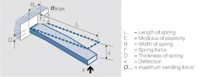
6.4.7 Contact Spring Calculations
Fig. 6.20:
One side fixed contact bending spring
L = Length of spring
E = Modulus of elasticity
B = Width of spring
F = Spring force
D = Thickness of spring
x = Deflection
max = maximum bending force
The influence of the dimensions can be illustrated best by using the single side fixed beam model (Fig. 6.20). For small deflections the following equation is valid:
where J is the momentum of inertia of the rectangular cross section of the beam
For springs with a circular cross-sectional area the momentum of inertia is
To avoid plastic deformation of the spring the max bending force σmax cannot be exceeded
The stress limit is defined through the fatigue limit and the 0.2% elongation limit resp.
and/or
- Triangular spring
- Trapezoidal spring
Deflection
Max. bending force
Deflection
Max. bending force

